background image

TO ADJUST THE THREAD TENTION DIAL

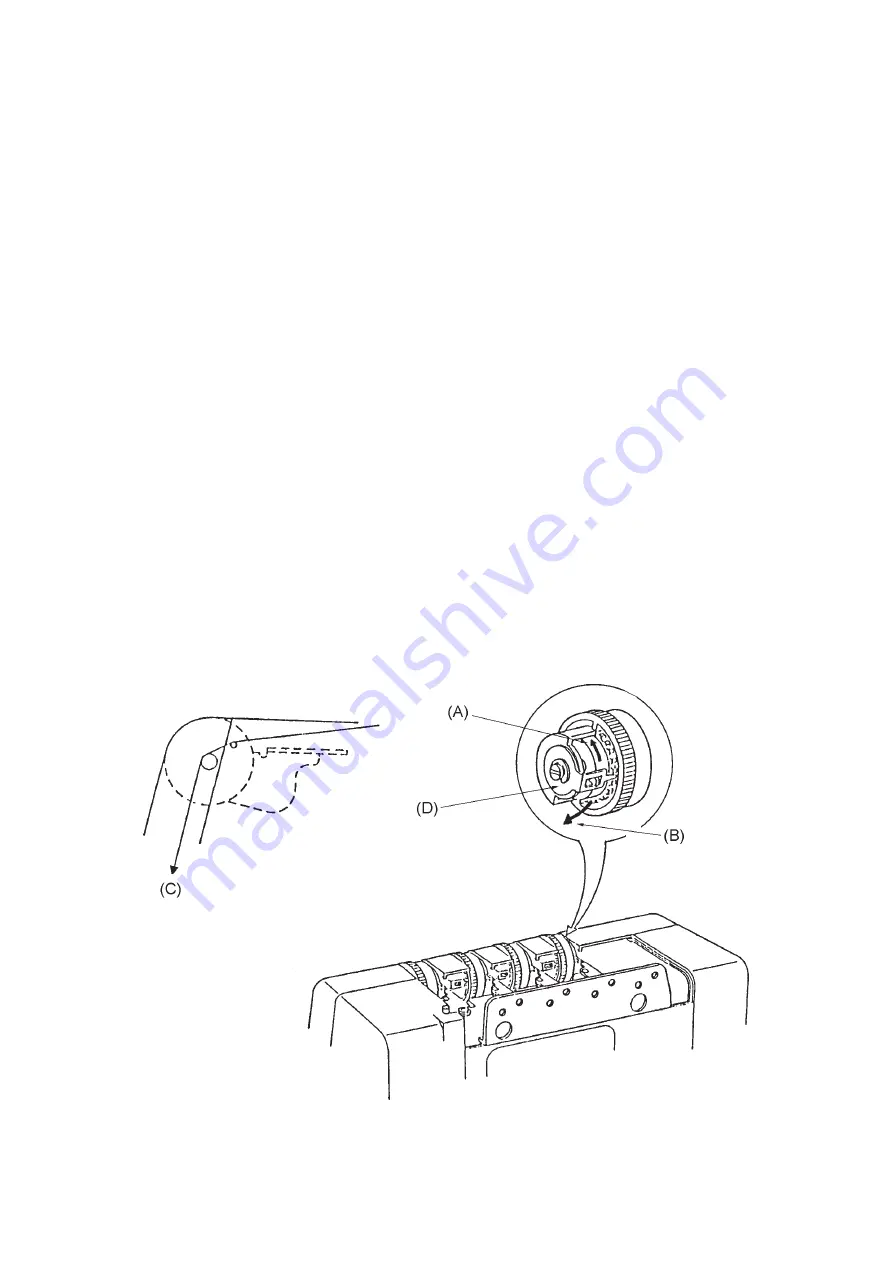
When each dial is set at “3” and No. 50 polyester filament thread (C) is used, the thread tension
should be as follows;

Needle (Left)

25 -  35 g

Needle (Right) 15 - 25 g
Upper looper

10 - 20g

Lower looper

20 - 30 g

When each dial is set at “9” and No. 50 polyester filament thread (C) is used, the thread tension
should be as follows;

Needle (Left)

125 g or more

Needle (Right) 60 g or more
Upper looper

55 g or more

Lower looper

120 g or more

To adjust:
1. Remove the top cover unit.
2. Match the scale “3” on the thread tension dial with the notch in the thread tension regulating

plate.

3. Adjust each thread tension with the adjusting plate (D).

* If the thread tension is higher than the above level, shift the adjusting plate (D) in the direc-

tion (A).

* If the thread tension is lower than the above level, shift the adjusting plate (D) in the direction

(B).

4. Match the scale “9” with the notch, and check if each thread tension is as specified.
5. Attach the top cover unit.

25

Summary of Contents for Mylock 634D

Page 1: ...SERVICING MANUAL MODEL 634D...

Page 2: ...UB THREAD TENSION DIAL 13 NEEDLE AND THE UPPER KNIFE TIMING 14 STITCH LENGTH 15 CLEARANCE BETWEEN NEEDLE AND LOWER LOOPER NEEDLE GUARDS 16 CLEARANCE BETWEEN NEEDLE AND FIXED NEEDLE GUARD 17 POSITION O...

Page 3: ...GE THE TOP COVER UNIT To remove 1 Loosen two screws A through hole of tension thread guide plate B and remove the top cover C To attach 2 Put the ribs D in tension cover unit E and tighten the setscre...

Page 4: ...NIT To remove 1 Open the looper cover unit A 2 Loosen set screw B and remove the setscrew C 3 Remove the belt cover unit D To attach 4 Put the ribs E F in front panel unit G and tension cover unit H a...

Page 5: ...remove 1 Remove face plate unit and belt cover unit 2 Remove setscrews A B and remove tension cover unit C To attach 3 Put rib D in front panel unit E and tighten the setscrews A B 4 Attached the bel...

Page 6: ...heel in counterclock wise 3 Remove set screws A B C D E and remove the front panel unit G To attach 4 Attach the front panel unit G and tighten setscrews A B C D E To set the thread take up lever posi...

Page 7: ...GE THE SIDE COVER UNIT To remove 1 Loosen setscrew A and remove the side cover unit B To attach 2 Fit the U groove C in the side cover unit B between the setscrew A and set plate D 3 Tighten the setsc...

Page 8: ...ge screws E and remove the base cushions F 2 Remove the machine base G To attach 3 Attach the machine base G and tighten the screws A B C D 4 Attach the base cushions F washers H I J and tighten the h...

Page 9: ...G and pull out the cord connectors A B C D To attach 3 Insert the cord connectors A B C D as shown below Connectors A Blue for motor B Brown for motor C Brown for lamp socket D Blue for lamp socket 4...

Page 10: ...at the highest position To adjust 1 Remove the face plate unit 2 Turn the balance wheel toward you with your hand and set the needle bar C at the highest position 3 Loosen the setscrew A to adjust th...

Page 11: ...ser bar lifter D is raised To adjust 1 Remove the face plate unit 2 Remove the set screws A to move the lamp socket unit E 3 Raise the presser bar lifter D and loosen the setscrew B Then adjust the pr...

Page 12: ...ub feed dog screws D 4 Push the main feed dog straight upward E and adjust the distance between the surface of needle plate and bottom of presser foot then tighten the setscrews 2 screws 5 When the to...

Page 13: ...ts downward motion by turning the balance wheel 6 Lower the presser foot and loose the two screws F and adjust the position of the feed cam S while aiming the guide line T Turn the feed cam to the dir...

Page 14: ...ger position is set at R position and remove the left needle and thread and adjust the sub thread tension dial as follows 1 When the lower looper thread tension is loose turn the adjusting screw E to...

Page 15: ...r knife timing Turn the upper knife drive cam G to the direction of D when the upper knife timing is delayed Turn the upper knife drive cam G to the direction of E when the upper knife timing is advan...

Page 16: ...l D at 1 0 2 Remove the face plate unit belt cover unit tension cover unit and front panel unit 3 If the actual stitch length is larger than 3 0 mm turn the adjusting screw E in the direction of A If...

Page 17: ...en the screw D and move the needle bar to the direction of E or F to get proper clearance between both needle and lower looper G Be careful not to change the needle bar height 5 Recheck the clearance...

Page 18: ...st 1 Remove the foot and the needle plate and lower the needle to its lowest position 2 Loosen the setscrew A and adjust the position of the fixed needle guard C When needle position setting knob is s...

Page 19: ...e level as the tip pin of the needle plate D To adjust 1 Remove the presser foot 2 Set the needle plate setting knob E at the guide line S on needle plate 3 Loosen 2 setscrews A and move chaining off...

Page 20: ...wheel toward you with your hand to bring the needle C 1 4 to 1 8 mm from its lowest position Loosen the hexagon bolt D just enough to move the lower looper driving arm E and move it until the tip of...

Page 21: ...oper shaft guide D and bottom of upper looper A The distance should be 1 6 to 1 8 mm E when the upper looper A is at the lowest position as show below 4 Tighten the hexagon bolt C Be careful not to ti...

Page 22: ...oper timing and the position of upper looper 2 Remove the machine base 3 Loosen the two setscrews F and adjust the timing by turning the upper looper drive cam G in the direction of A If the timing of...

Page 23: ...preader holding plate F 2 Turn the balance wheel toward you with your hand to bring the loopers as shown in B 3 Loosen the setscrew G and adjust the clearance by moving the upper looper H to the back...

Page 24: ...n the left 0 2 to 0 05 mm at the needle on the right To adjust 1 Turn the balance wheel toward you with your hand to bring the needle just behind the upper looper A in downward travel 2 Loosen the set...

Page 25: ...of upper knife should be 0 8 to 1 5 mm D below the edge of lower knife To adjust 1 Before proceeding with this adjustment check the upper knife timing 2 Loosen the 2 setscrews B and adjust the lower...

Page 26: ...read guide D so that the hole of thread guide E is in line with the groove of lower looper G as shown in F Looper Thread Guide Lower Loosen the setscrew B and set so that the bottom side of the looper...

Page 27: ...ht 60 g or more Upper looper 55 g or more Lower looper 120 g or more To adjust 1 Remove the top cover unit 2 Match the scale 3 on the thread tension dial with the notch in the thread tension regulatin...

Reviews: