background image

Page 43

ENGLISH


Installation and Operation Manual   

|

   Jandy® Legacy™ Model LRZE Pool/Spa Heater by Zodiac®

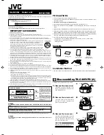
Figure 28. test Point identification diagram

IGNITION CONTROL

24

VAC

FV+ FV-

IGN

120 L1 L2

IGN

FS

W

GND

VAL

IGN

240

W

BK

R

BK

B

HOT SURFACE 

IGNITER

W

FLAME SENSE

BK

GAS

VALVE

USER INTERFACE1

BK O BL R

HIPRESS/

HILIMIT

LOPRESS/

FUSELINK

WATER

PRESS

REMOTE

SPA POOL COM

24VAC

COMP/

IGN

FAN/

LOUVER

UNIVERSAL CONTROLLER

POWER INTERFACE

UNIVERSAL CONTROLLER

USER INTERFACE

POWER INTERFACE

BK O BL R

WATER PRESS

SWITCH

130°F (55°C)

LIMIT SWITCH

150°F (65°C)

LIMIT SWITCH

ROLL-OUT

SWITCH

(FUSIBLE

LINK)

GAS VALVE

B

B

B

B

B

B

B

B

B

B

B

B

B

B

B

B

B

B

B

B

B

B

BK

R

B

B

B

B

B

B

B

B

B

B

B

B

B

BK

G

R

240 VAC

HEATER

POWER

SUPPLY

R

Y

R

Y

R

Y

R

Y

24 VAC

R

Y

R

Y

TRANSFORMER

W/R

W/BK

Y/BK

R

Y

Y

BR

WATER

TEMP

WATER

TEMP

SENSOR

BK

BK

BK

BK

O

BL

GR

V

BR

Y

BR

Y

Y/BK

FUSE

                      Factory Wired 24V

                      Factory Wired 120V/240V

                      Optional 120V Wiring


BK - BLACK

BL - BLUE

BR - BROWN

G - GREEN

GR - GRAY

O - ORANGE

R - RED

V - VIOLET

W - WHITE

W/BK - WHITE WITH BLACK TRACE 

W/R - WHITE WITH RED TRACE 

Y - YELLOW

Y/BK - YELLOW WITH BLACK TRACE

ALTERNATE 120 VAC WIRING

120 VAC

HEATER

POWER

SUPPLY

G

R

BK

IGN

120

IGN

240

24 VAC

R

Y

TRANSFORMER

W/BK

R

G

R

BK

24 VAC

R

Y

R

G

R

BK

24 VAC

R

Y

R

G

R

BK

24 VAC

R

Y

R

G

R

BK

24 VAC

R

Y

BK

R

G

R

BK

24 VAC

R

Y

W/R

R

W

Ignition Control

L1

BK

W

HOT SURFACE 
IGNITER

W

464°F (

240°C)

VENT 

TEMPERATURE 

LIMIT

BK

BL

1

2

3

4

5

6

7

8

9

10

11

12

13

14

15 16

Summary of Contents for LRZ Electronic

Page 1: ...per installation and or operation can create carbon monoxide gas and flue gases which can cause serious injury property damage or death For indoor installations as an additional measure of safety Zodiac Pool Systems Inc strongly recommends installation of suitable Carbon Monoxide detectors in the vicinity of this appliance and in any adjacent occupied spaces Improper installation and or operation ...

Page 2: ......

Page 3: ...17 5 4 Reversible Water Connections 17 5 5 Connections at Heater 19 5 6 Pressure Relief Valve and Temperature Relief Valve 20 5 7 Auxiliary Components Chlorinators Ozone Generators and Sanitizing Chemicals 21 Section 6 Electrical 22 6 1 General Information 22 6 2 Main Power 22 6 3 Bonding 24 6 4 Optional Remote Controls 24 6 4 1 Connection to a Remote Pool Off Spa Selector 3 Wire Connection 24 6 4...

Page 4: ...tion 38 10 4 Electrical Troubleshooting 39 10 4 1 Electrical Power Supply 39 10 4 2 Controller 40 10 4 3 Control Circuit Troubleshooting 40 10 4 3 1 Transformer 40 10 4 3 2 Fuse 40 10 4 3 3 Water Pressure Switch 40 10 4 3 4 Roll Out Switch Fusible Link 40 10 4 3 5 Temperature Limit Switches Circuit 41 10 4 3 6 Gas Valve Voltage 41 10 4 3 7 Igniter Ignition Control Circuit 41 Section 11 Replacement...

Page 5: ...ended by the U S Consumer Product Safety Commission should be observed when using the spa AVERTISSEMENT Les Règlements suivants pour Cuves Thermales tel que recommandés par la Commission U S de Sécurité des Produits pour les Consommateurs devraient être respectés lors de l utilisation du spa WARNING The U S Consumer Product Safety Commission warns that elevated water temperature can be hazardous C...

Page 6: ... Make all warranty claims to an authorized Jandy representative or directly to the Zodiac Pool Systems Inc factory Claims must include the heater serial number and model this information can be found on the rating plate installation date and name of the installer Shipping costs are not included in the warranty coverage The warranty does NOT cover damage caused by improper assembly installation ope...

Page 7: ... are available from any Jandy distributor 2 Primer and cement suitable for cementing CPVC pipe to PVC pipe and an appropriate coupling for connecting the factory supplied CPVC pipe nipples to PVC pool plumbing 3 A noncombustible platform for installation on combustible surfaces see Section 2 3 3 Noncombustible bases are available from your Jandy distributor 4 A factory approved vent cap for all ou...

Page 8: ...Technical Support Department at 800 822 7933 See Section 11 Parts List of this manual for the correct kit number for the manifold assembly needed for your altitude Table 1 defines the altitude designations as described by the Standard for Gas Fired Pool Heaters ANSI Z21 56 in the United States and Gas Fired Appliances For Use At High Altitudes CAN 1 2 17 in Canada 1 7 2 Dimensions See Figure 1 for...

Page 9: ...tified for installation in an outdoor shelter in Canada when equipped with a draft hood An outdoor shelter is an enclosure not normally occupied which does not communicate directly with occupied areas Check the rating plate on the heater or the Parts List Section 11 of this manual for the correct Jandy draft hood or vent cap part number See instructions supplied with the draft hood or vent cap for...

Page 10: ... covered with sheet metal at least 24 gauge thick and extending beyond the full width and depth of the heater by at least six 6 inches 153 mm in all directions The masonry must be laid with ends unsealed and joints matched to provide free circulation of air from side to side through the masonry see Figure 2 If the heater is installed in a carpeted alcove the entire floor of the alcove must be cove...

Page 11: ...i de hauteur La partie sous la saillie doit être ouverte sur 3 côtés If the heater is installed close to a structure protect it from rain water runoff with rain gutters on the roof or other measures Do not locate the heater near irrigation sprinkler systems that could spray water on it Water from sprinklers may cause damage to controls and electronic components Avoid locations where wind deflectio...

Page 12: ... internal air for combustion Combustion air should be ducted to the heater from outside the structure Outside Air Supply When combustion air is supplied directly through an outside wall each opening should have a minimum free area of one square inch per 4 000 BTU h 1 2kW input of the total input rating of all appliances in the enclosed area If air is provided through horizontal ducts each opening ...

Page 13: ...Z223 1 NFPA 54 latest edition pay particular attention to the chapter addressing Venting of Equipment Applicable provisions of additional applicable local building codes may also need to be followed WARNING Do not store any chemicals cleaners or other corrosive material near combustion air openings or in the room Avoid locating appliance vents in the vicinity of combustion air openings Failure to ...

Page 14: ...a to CAN CSA B149 1 for more information on multiple venting 3 2 3 Inspection and Replacement of Existing Vent System with New Components If the Legacy Model LRZ electronic is being installed to replace an existing pool heater it is recommended that a new appropriate venting system be installed with the new heater However if an existing venting system must be used be sure to carefully inspect the ...

Page 15: ...s Distance from Gas Meter Heater Size 0 50 feet 0 15 m 50 100 feet 15 30 m 100 200 feet 30 60 m in mm in mm in mm 125 3 4 19 1 25 1 25 175 1 25 1 25 1 1 4 32 250 1 25 1 1 4 32 1 1 4 32 325 1 1 4 32 1 1 4 32 1 1 2 38 400 1 1 4 32 1 1 2 38 1 1 2 38 NOTES 1 These numbers are for natural gas 0 65 Sp Gr and are based on 1 2 inch 3 45 kPa water column pressure drop Check supply pressure with a manometer...

Page 16: ... Consult the National Fuel Gas Code NFPA 54 ANSI Z223 1 latest edition the Liquefied Petroleum Gas Code NFPA 58 latest edition the Natural Gas and Propane Installation Code in Canada CAN CSA B149 1 latest edition and any other local codes and fire protection authorities about specific installation restrictions in your area For ALL installations the combustion air openings requirements of Table 3 a...

Page 17: ...shipped with water connections on the right side but can be modified in the field to provide left side water connections This procedure involves removing the heat exchanger headers and reinstalling them on opposite ends of the tube assembly Some of the heater wiring must be disconnected and re routed so this procedure must be done only by a trained service technician Heat exchanger reversals are g...

Page 18: ...s free from the header outside of the cabinet 6 Disconnect the two WATER TEMP tempera ture sensor leads from the Power Interface board on the raceway Clip any wire ties attached to the harness Pull the wires out of the cabinet so that they hang free from the header outside of the cabinet 7 Disconnect the yellow Water Press two pin connector from the Power Interface board on the raceway Clip any wi...

Page 19: ...o the yellow Water Press connector on the Power Interface board 22 Use plastic wire ties to refasten the temperature sensor high limit switch and water pressure switch wires to each other Bundle the wires near the control panel and fasten them with a wire tie ATTENTION Afin d empêcher des dégâts matériels ou des blessures assurez vous qu aucun des fils n est en contact avec un bord tranchant ou un...

Page 20: ...ited Sates or CSA 4 4 in Canada Follow these steps to install a pressure relief valve 1 To protect the threads while drilling screw the brass adapter included with the Jandy PRV kit into the blind threaded hole on the top of the inlet outlet header 2 Using the countersink in the center of the blind hole as a guide drill a 1 4 inch hole through the plastic See Figure 13 3 Open the hole by reaming i...

Page 21: ...vertightening may crack the header Route the discharge piping so that discharge from the pipe does not endanger anyone near the heater Refer to your local installation codes for more detailed information The valve setting should be at or below the maximum working pressure of any component in the filter system The maximum working pressure of the Legacy Model LRZ electronic heater is 75 psig 5 7 Aux...

Page 22: ...ust include a definite means of grounding There is a bonding lug on the right side of the heater where a bond wire must be attached 6 2 Main Power Electrical wiring must be in accordance with the latest edition of the National Electric Code NEC ANSI National Fire Protection Association NFPA 70 unless local code requirements indicate otherwise In Canada the Canadian Electrical Code CEC CSA C22 1 No...

Page 23: ...E LINK GAS VALVE B B B B B B B B B B B B B B B B B B B B B B BK R B B B B B B B B B B B B B BK G R 240 VAC HEATER POWER SUPPLY R Y R Y R Y R Y 24 VAC R Y R Y TRANSFORMER W R W BK Y BK R Y Y BR WATER TEMP WATER TEMP SENSOR BK BK BK BK O BL GR V BR Y BR Y Y BK H03028000 Rev J FUSE Factory Wired 24V Factory Wired 120V 240V Optional 120V Wiring BK BLACK BL BLUE BR BROWN G GREEN GR GRAY O ORANGE R RED ...

Page 24: ...t not limited to pump motors and heaters be bonded together as part of the equipotential bonding grid Zodiac provides a special labeled bonding lug on the right side of the heater to accommodate this requirement 6 4 Optional Remote Controls WARNING RISK OF ELECTRIC SHOCK WHICH CAN RESULT IN SERIOUS INJURY OR DEATH Before attempting installation or service ensure that all power to the device is dis...

Page 25: ...terminal See Figure 18 5 Restore power to the heater and the pool spa control system NOTE If you install a time clock to control the filter pump operation it is recommended that the time clock have its own low voltage Fireman s switch to turn off the heater before turning off the pump The switch should shut off the heater about 15 minutes before the filter pump shuts off This will allow for a more...

Page 26: ...urfaces can cause serious burns Do not touch these surfaces while the heater is in operation AVERTISSEMENT Les tuyaux d aération et le dessus de l appareil deviennent chauds Ils peuvent causer de graves brûlures Ne touchez pas à ces surfaces lorsque l appareil est en marche CAUTION Do not use this heater if any part has been under water Immediately call a qualified service techni cian to inspect t...

Page 27: ...ter system and heater operate continuously until the water reaches the temperature setting on the temperature control When that happens the heater will automatically shut off but the filter pump will keep running 7 3 Operating the Controller Your new Legacy Model LRZ electronic Pool Heater is controlled by an advanced microprocessor based controller that provides a sophisticated yet simple interfa...

Page 28: ...ng is displayed To turn the spa on or off indefinitely press the MENU button to select To select the length of time for the spa to run use the Up or Down button to scroll to display SELECT SPA TIMER TIME SELECTION Press the MENU button to select The display SELECT SPA TIME 01 00 HRS default time setting is displayed Use the Up or Down button to select the length of time for the spa to run between ...

Page 29: ...ter to the pool is very short The back pressure could be too low to trigger the pressure switch If this happens it may be necessary to install a directional fitting or elbows where the return line enters the pool This will increase back pressure enough for the heater to operate properly 7 6 Lighting and Shutdown Procedures WARNING Do not attempt to light the heater with the door off Doing so may c...

Page 30: ...ez le contrôleur à ARRÊT 2 Couper toute arrivée de courant de l appareil s il doit subir une réparation 3 Tourner le bouton de commande du gaz dans le sens horaire jusqu à OFF 4 Remettre le panneau d accès aux commandes couPuRe de L aRRiVÉe de GaZ de L aPPaReiL Voir le manuel pour les détails concernant l opération du contrôle de thermostat 1 STOP Read the safety information above on this label 2 ...

Page 31: ...to change the temperature rise for optimum performance and length of heater life The bypass assures constant heat exchanger flow even though flow through the filter system will vary depending on how dirty the filter is For most installations an external bypass valve is not needed in the heater water piping This is due to the large size of the heater s internal bypass valve If the pump flow rate is...

Page 32: ...a larger pump Before proceeding with either remedy verify proper heater operation Low gas input results in low temperature rise and vice versa A problem with the heater internal bypass assembly also affects measured temperature rise Section 8 Maintenance 8 1 Water Chemistry The mineral content of swimming pool water increases daily due to natural evaporation and the addition of sanitizing chemical...

Page 33: ...eater before the first frost See Figure 24 5 After all water has drained from the heater check for mineral buildup in the openings 6 Use compressed air to blow out any standing water remaining in the heat exchanger 7 Inspect the gaskets on the drain plugs and reinstall plugs but do not tighten 8 Disconnect the pressure switch from the copper tubing See Figure 25 8 2 3 Spring Start up To restart th...

Page 34: ...o make sure that water runs freely through it If corrosion is found replace the pressure relief valve When replacing the valve be sure that the pump is off Install the valve so that the discharge is directed away from any area that may be damaged by water 4 Be sure all combustion air and ventilation openings are not blocked Check for spider webs and other debris inside the heater in the vents on a...

Page 35: ...urner surface See Figure 26 9 Perform a temperature rise test in accordance with Section 7 8 Section 9 Troubleshooting 9 1 General Heater Troubleshooting Table 8 lists some of the more common problems causes and solutions encountered when running the heater Most problems occur when the heater is being started for the first time after installation or at spring start up Careful installation and main...

Page 36: ...L listed vent cap 4 Flame has lazy yellow tip A Low primary air low gas pressure A Correct manifold pressure according to rating plate Correct lazy yellow tip orifice size if necessary see parts list Clean burner ports if dirty 5 Not enough heat A Inadequate gas supply B Low manifold gas pressure C Heater size inadequate D Temperature rise set incorrectly A Gas meter too small Gas line from meter ...

Page 37: ...fusible link Check for and correct any downdraft condition Refer to qualified service personnel 2 Identify and correct loose connections or replace vent temperature limit Refer to qualified service personnel FAULT CHECK IGN CONTROL 1 Air flow restricted at intake or discharge 2 Oscillating pump pressure 3 Low gas supply pressure 4 No flame at burners 1 Check for proper clearances around heater and...

Page 38: ...nents in the pool system including pump filters and strainers water valves gas supply electrical power and time clocks have an affect on heater operation Confirm that the heater control is set to either POOL or SPA and that the corresponding temperature set point is set high enough to make the heater operate Make sure the pump is operating that the filter and strainers are not clogged that there a...

Page 39: ...ner tray by a sheet metal bracket Excessive tempera ture in the component compartment possibly due to a blocked flue or flame roll out will cause the switch to fail This opens the safety circuit which shuts off the gas valve and shuts the heater down 9 Vent Temperature Limit This is a single use switch which detects abnormal temperature in the vent system It is mounted to the flue collector assemb...

Page 40: ...enters the two pin connector on the controller If there is not 20 28 Volts AC nominal at this point either the controller or the two pin wire harness is faulty and must be replaced If 20 28 Volts AC nominal is detected at test point 4 then move the red lead of the meter to test point 5 where the gray wire from the Pressure Switch enters the two pin connector If 20 28 Volts AC nominal is detected a...

Page 41: ...he 150 F 65 C limit is bad and should be replaced If the meter reads 20 28 Volts AC nominal move the lead to the terminal of the 130 F 55 C limit that is connected to the wire that jumps between the two limit switches No voltage here means that the wire assembly is bad and needs to be replaced 20 28 Volts AC nominal shows that the wire between the two limits is making a good connection Now move th...

Page 42: ...rt on the right side of the combustion chamber If the correct voltage is detected between points 13 and 10 or points 12 and 10 during the trial for ignition but the igniter does not glow check the connections to the igniter Check the igniter with the ohmmeter Disconnect the IGN120 or IGN240 terminals from the ignition control and the connector at test point 10 Place one lead of the meter on each w...

Page 43: ...B B B B B B B B B B B B B B B B B BK R B B B B B B B B B B B B B BK G R 240 VAC HEATER POWER SUPPLY R Y R Y R Y R Y 24 VAC R Y R Y TRANSFORMER W R W BK Y BK R Y Y BR WATER TEMP WATER TEMP SENSOR BK BK BK BK O BL GR V BR Y BR Y Y BK FUSE Factory Wired 24V Factory Wired 120V 240V Optional 120V Wiring BK BLACK BL BLUE BR BROWN G GREEN GR GRAY O ORANGE R RED V VIOLET W WHITE W BK WHITE WITH BLACK TRAC...

Page 44: ...Complete Copper 125 400 R0470601 05 44 Heat Exchanger Assembly Complete CuNi 125 400 R0500701 05 45 Heat Exchanger Drain Plugs 2 Polymer All R0446000 Key No Description Model No Order Part No Water System Polymer Continued 46 3 Coupling Nut Kit w O ring All R0454000 47 Bypass Assembly Polymer 125 400 R0453701 48 Bypass Spring Adjustable Polymer All R0453901 49 Tailpiece w Union Nut Set of 2 Polyme...

Page 45: ...tion and Operation Manual Jandy Legacy Model LRZE Pool Spa Heater by Zodiac 11 3 General Exploded View 35 36 37 32 31 33 34 75 20 22 81 80 42 44 41 69 76 88 77 78 85 83 69 29 82 1 72 71 86 73 4 79 28 84 70 12 11 69 74 87 39 40 ...

Page 46: ...46 ENGLISH Jandy Legacy Model LRZE Pool Spa Heater by Zodiac Installation and Operation Manual 11 4 Detailed Exploded View 27 14 13 11 7 2 8 3 10 45 63 65 66 46 17 18 15 16 45 25 26 23 49 47 6 5 70 48 24 19 ...

Page 47: ...Page 47 ENGLISH Installation and Operation Manual Jandy Legacy Model LRZE Pool Spa Heater by Zodiac 58 59 55 56 61 23 26 25 15 16 54 53 61 63 65 66 63 52 57 20 60 52 51 50 62 68 41 ...

Page 48: ...nal S A S U used under license All trademarks referenced herein are the property of their respective owners 2012 Zodiac Pool Systems Inc H0299500 Rev J 1202 Zodiac Pool Systems Inc 2620 Commerce Way Vista CA 92081 1 800 822 7933 www ZodiacPoolSystems com ...

Reviews: