Page 9
a
Figure 4. By-Pass Installation Configuration
Connecting the Chlorinator
5.
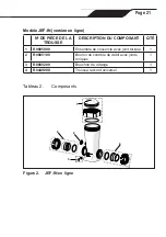
Place the o-ring (5a) on the 1/4” check valve fitting (5b) and thread
into the outlet side of the feeder. Do not over-tighten the fitting.
6.
Place the flat rubber gasket (4x missing on diagram) onto the control
valve (5d). Place a small amount of teflon tape (not included) onto the
valve threads.
7. Thread the control valve into the feeder on the inlet side. Do not over-
tighten.
8. Connect a section of the black tubing for the feeder inlet (5c) to the
hose barb on the control valve (5d).
9.
Use one of the hose clamps (5f) to secure the tubing to the fitting. Do
not over-tighten the hose clamp.
10. Connect a section of the black tubing for the feeder outlet (5e) to the
hose barb on the check valve (5b).
11.
Use one of the hose clamps (5f) to secure the tubing to the fitting. Do
not over-tighten the hose clamp.


