Page 8
NOTE:
In installations with a flow of greater than 50 g.p.m. (189.3 l.p.m),
install the unit on a by-pass to allow the correct adjustment of the
dosing rate and to avoid damage to the unit caused by excess flow.
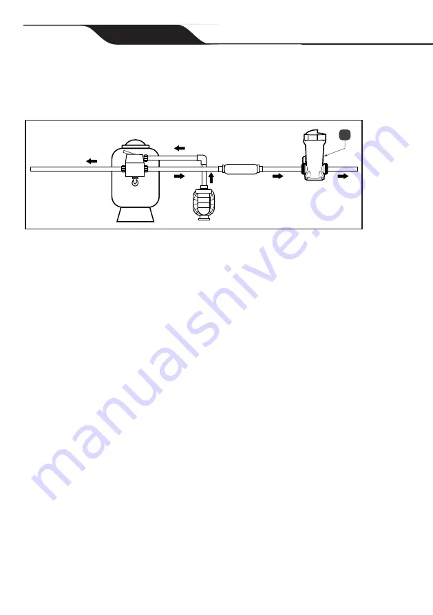
Figure 3. In Line Installation Configuration
a
Section 4. By-Pass Installation (JEF-OFF)
NOTE:
There are two versions of the plumbing nipples included with this
feeder: one for use with 1 1/2” (50mm) PVC (Figure 4) and one for
2” (63mm) PVC.
1.
Position the dosing unit on a level surface as close to the filter and
pump as possible.
Do not install in copper plumbing.
2. The inlet connection must be made in the pipework between the pump
and filter. This connection will feed water into the dosing unit.
3. The outlet connection must be made down-stream of the heating
system or, if no heating system is installed, down-stream of the filter,
see Figure 4(a). This connection will be feeding treated water from the
dosing unit into the plumbing system.
4. Cut the dosing tube to the required lengths, ensuring the cuts are
clean, square and free of burrs.


