IM800-06
www.ueonline.com
WIRING
DISCONNECT ALL SUPPLY CIRCUITS BEFORE WIRING. ELECTRICAL
RATINGS STATED IN LITERATURE AND ON NAMEPLATE SHOULD
NEVER BE EXCEEDED. OVERLOAD ON A SWITCH CAN CAUSE FAILURE
ON THE FIRST CYCLE. WIRE UNITS ACCORDING TO LOCAL AND NATIONAL
ELECTRICAL CODES. MAXIMUM RECOMMENDED WIRE SIzE IS 14 AWG.
Types 800, 802
Connect the electrical conduit to the case securing it with the grounding
locknut supplied.
Note:
Unless control is connected to a metallic conduit, grounding bushing
should be removed from grounding wire. A separate conductor should be pro-
vided from grounding system directly to the non-current carrying metal parts of
control (splice the grounding wire).
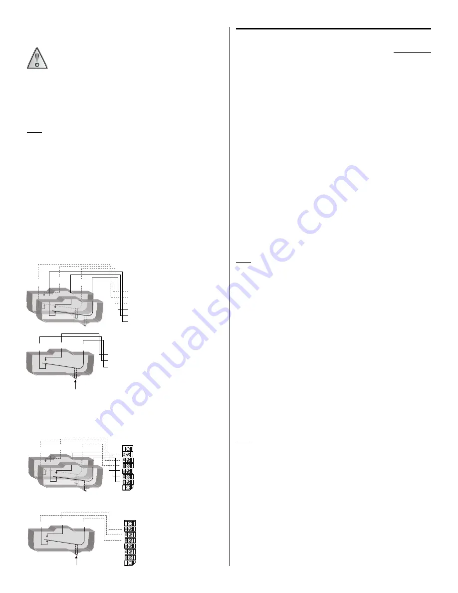
Conduit opening is available on the left side as standard. It can be supplied on
the right side on request. Wire through the 7/8” conduit hole directly to the
lead-wire(s) provided, color coded as follows, or to the optional terminal block.
Switch 1
Switch 2
Common
Violet
Yellow
Normally Open
Blue
Orange
Normally Closed
Black
Red
See wiring Diagrams Figure 2A and 2B.
Part II - Adjustments
Tools Needed
5/64” Allen Wrench
5/16” Open End Wrench (2 required)
Phillips and slotted tip screwdriver
Single Switch Type 800
Move the set point Adjustment Pointer (red) up scale beyond the black
Indicating Pointer. This permits checking the set point by moving the lever
arm upward with a finger or tool simulating thermal assembly movement.
Connect test lights to indicate switch operation or listen for the switch to
click. Loosen adjustment “A” and move the Adjustment Pointer until it
agrees with the Indicating Pointer. When the switch clicks re-tighten the
screw.
Dual Switch Type 802
Type 802 has a separate knob and pointer for each switch. Turn black knob
for switch #2 and turn green inserted knob for switch #1. Set points are
shown by individual pointers and may be separated up to 100% of dial range
apart, so long as the red pointer is set higher than the green pointer.
To align either switch to the Adjustment Pointer the corresponding adjustment
“A” must be loosened and the Adjustment Pointer set to the Indicating Pointer,
then tighten adjustment “A”.
Note:
Switch #1, green pointer, cannot be set to operate at a higher setting
than switch #2, red pointer.
Connect test lights to indicate switch operation or listen for the individual
switch clicks. The separation between switches is the difference between the
high and low set points. The set points are determined by setting individual
adjustment pointers and may be separated up to 100% of scale range apart.
Replace cover and adjustment knob if removed during installation. Controller
is ready for operation. Turn setting pointer to desired control temperature
and start up the process. To suit particular process conditions or for greater
controller accuracy it may be desirable to make slight alterations to the set
point or indicator reading. Procedures for making these adjustments are
described below.
In-Process Adjustments
Use an accurate test thermometer such as a thermocouple with its probe
mounted directly to the center of the sensing bulb. Before making any
adjustments, allow process temperature to stabilize; i.e., successive on-off
cycles repeated.
Note:
Prior to making any controller adjustments, the cover and adjustment
knobs should be removed. The adjustment knob slides off adjustment shaft
for all controls except the 802. The 802 requires a 5/64” allen wrench. When
adjustments are completed, all applicable parts should be replaced.
Correct any difference between the Indicating Pointer and the test ther-
mometer by holding the compensator with a 5/16” wrench while turning the
zero adjustment “C” on the thermal assembly with a second 5/16” wrench,
per Figure 3 until the brown Indicating Pointer reads the same as the test
thermometer. Turning clockwise lowers indicated reading. Compare the pro-
cess temperature with the set point Adjustment Pointer. Loosen adjustment
screw “A” to align set point Adjustment Pointer with the Indicating Pointer.
Re-tighten screw “A”.
N.C.
N.O.
COM.
N.C.
N.O.
COM.
ORANGE
RED
YELLOW
VIOLET
BLUE
BLACK
Figure 2A -
Dual Switch
N.C.
N.O.
COM.
Plunger
BLUE
BLACK
VIOLET
Figure 2B -
Single Switch
N.C.
N.O.
COM.
N.C.
N.O.
BLUE
BLACK
VIOLET
ORANGE
RED
YELLOW
COM.
DUAL SWITCH
BLUE
BLACK
VIOLET
SINGLE SWITCH
N.C.
N.O.
COM.
Plunger
Figure 2C -
Terminal Block option
Optional terminal block wiring is available for single or dual switch controls
(option M100). See Figure 2C
(Refer to Figure 3)
36
Summary of Contents for 700E
Page 2: ...SN _______________...
Page 4: ......
Page 6: ......
Page 8: ......
Page 22: ...BLANK PAGE 14...
Page 28: ...BLANK PAGE 20...
Page 30: ...22...
Page 31: ...Low Volume Exhaust Fan Eyebrow Hood Figure 3 23...
Page 32: ...24...
Page 33: ......
Page 34: ...BLANK PAGE 26...
Page 36: ...28 Figure 7...
Page 37: ......
Page 38: ...BLANK PAGE 30...
Page 39: ...31...
Page 40: ...BLANK PAGE 32...
Page 41: ...33...
Page 42: ...BLANK PAGE 34...
Page 47: ...39...
Page 48: ...40...
Page 49: ...41...
Page 50: ...42...
Page 51: ...43...
Page 52: ...44...
Page 53: ...45...
Page 54: ...46...
Page 55: ...47...
Page 56: ...BLANK PAGE 48...
Page 58: ...BLANK PAGE 50...
Page 59: ...51...


