background image

13

IMPORTANT - Before putting the applicator into operation, check the machine for damaged or worn parts and 

replace as necessary.

Wheel Nuts Tightened

During initial operation, tighten standard 3/4” wheel studs and nuts to torque 400 ft-lbs.  Re-check wheel nut torque settings during 

initial break in period (10, 20, 50 acres), then every 10 hours of use for the first 40 hours. Continue checking wheel nut settings until nuts 

do not loosen.  If wheel nuts loosen, they may damage wheel nut seats. Once seats are damaged, it will become impossible to keep nuts 

tight.

Failure to keep the wheel nuts tight could cause considerable damage to the applicator and surrounding.  It is the dealer’s 

responsibility to torque the wheel nuts to specification before delivery.  Damage caused by failure to keep wheel nuts tight is not 

warrantied. 

Tires Inflated

Ensure tires are inflated to the correct pressure, as indicated in “Operation” on page 17.

Hardware

Inspect the unit for loose nuts, bolts, and fasteners. Tighten where necessary.

Grease Points

Check all bearings and grease fittings for proper lubrication, according to the operator’s manual.

Hydraulic Leaks

Unfold and fold the applicator according to the fold instructions decal on the tongue of the applicator or in the operator’s manual. Check 

for leaks on hydraulic cylinders, fittings, and hose ends (Use cardboard or wood to safely check for leaks) and tighten where necessary.

Clean Tank

Check tank for debris (like plastic shavings from assembly) and clean if necessary.  Use a vacuum to remove tank debris.

Indicator Balls

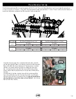
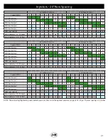
Remove all indicator balls from flow monitors and install the correct indicator ball in each flow monitor for the customer’s desired gallons 

per acre and speed.  Refer to “Flow Monitor Set Up” on page 19 to determine which indicator ball to select.

Water Test

Fill tank with 100 gallons of water and test applicator with water before use.  Most rate controllers have a “self-test” mode that for this 

purpose.  Tighten any leaking hose or fitting connections.  

Do not run the fertilizer pump dry.


This could cause permanent failure to 

the fertilizer pump and is not warrantied.

Winterization

If applicator has ever had fluid in the tank, winterize the applicator before the temperature drops below freezing.  See “Storage” on page 

33 for winterizing instructions.  

Failing to winterize applicator can cause severe damage to fertilizer distribution components 

and is not warrantied.

Defects & Scratches

Examine paint and poly tank for scratches, cracks, gouges, and defects.

Safety Decals & Lights

Check that safety decals, reflective decals, and the slow-moving vehicle sign are properly located. Refer to the operator’s manual for 

proper placement of decals.  Ensure all lights function properly.

Pre-Operation Checklist

Summary of Contents for NITRO-GRO 5010

Page 1: ...J M Manufacturing Co Inc 284 Railroad Street P O Box 547 Fort Recovery OH 45846 Ph 419 375 2376 Fax 419 375 2708 www jm inc com Rev 1 23 2020 O P E R A T O R S M A N U A L MODEL Manual...

Page 2: ...l Ground Driven Pump 12 Pre Operation Checklist 13 Hitching and Unhitching the Applicator 14 Connecting the Hydraulic Hoses 14 Folding Unfolding 14 Transporting 15 Wheel Spacing 16 Operation 17 Troubl...

Page 3: ...Manifold Hydraulic Pump Only 52 Check Valve 53 Tank 54 Gauge Wheel 55 Hydraulic Schematic 56 Wire Harness 58 SCS 450 Liquid Control System 59 ISO Liquid Control System 60 Fertilizer Hose Routing Hydr...

Page 4: ...cient maintenance or iv normal wear or tear This warranty does not cover products that are previously owned and extends solely to the original purchaser of the product Should the original purchaser se...

Page 5: ...RTANT is used to indicate that failure to observe can cause damage to equipment The terms CAUTION WARNING and DANGER are used in conjunction with the Safety Alert Symbol a triangle with an exclamation...

Page 6: ...local laws and regulations A frequent cause of personal injury or death is from persons falling off equipment and being run over Do not permit persons to ride on this machine Travel speeds should be s...

Page 7: ...0 80 ft lbs 9 16 18 170 ft lbs 5 8 18 350 ft lbs 3 4 16 400 ft lbs 20mm 475 ft lbs 22mm 640 ft lbs Always tighten hardware to these values unless a different torque or tightening procedure is listed f...

Page 8: ...l Quick Fill 2 Fill Standard 3 Fill Optional 2 Fill Standard 3 Fill Optional Wash Tank Standard 9 Gallon Wash Tank Standard 9 Gallon Wash Tank Specifications Other Row Spacing Available Upon Request T...

Page 9: ...ransparent inspection tube Each coulter is connected with a separate supply hose Hitch Coulter Holding Tank Gauge Wheel Rinse Tank Light Bar Tank Fill Valve 2 or 3 Hydraulic Pump Flow Monitors Optiona...

Page 10: ...ctor hydraulic flow to the pump damage will occur See Set Up Instructions in the pump manual The PWM valve controls the hydraulic flow to the pump which creates a variable rate pump With the PWM valve...

Page 11: ...of rows usually one less or one more So the number of rows will be even and the number of coulters will be odd since you are placing the nitrogen between the rows Example a 16 row unit will have eith...

Page 12: ...issue the agitation valve may be opened to allow air to escape from the pump so it can be primed The agitation valve can also be used to evenly mix additives by running the pump with the electronic co...

Page 13: ...ck for leaks on hydraulic cylinders fittings and hose ends Use cardboard or wood to safely check for leaks and tighten where necessary Clean Tank Check tank for debris like plastic shavings from assem...

Page 14: ...he wing assemblies On 40ft units one cylinder will unfold the inner wing section and another cylinder will unfold the outer wing section The inner wing will automatically fold to the wing kick up posi...

Page 15: ...e When transporting applicator do not exceed 10 MPH in the field or over rough terrain For highway transportation do not exceed 20 MPH Reduce transport speed when necessary to maintain full control Ne...

Page 16: ...spacing at 132 When shipped the light bar will be attached using holes A and B The light bracket needs to be positioned so that the Amber light is out past the wheel NOTE When changing the wheel spaci...

Page 17: ...he agitation valve is open to allow the pump to prime NEVER run the pump dry 8 With the maintenance valve open perform initial setup of the pump as outlined in the pump operator s manual After pump se...

Page 18: ...stment knob clockwise IMPORTANT Do not exceed 1 350 psi Center toolbar section set too deep Add cylinder spacers to lift cylinders Wings are tilted down from center toolbar section Gauge wheels set to...

Page 19: ...arts on pages 20 31 decide which ball is best suited for your desired GPA and Speed Only choose one ball for all flow monitors Remove the balls that are not being used The easiest way to remove the ba...

Page 20: ...psi 15 23 33 41 50 59 70 78 88 20 28 40 48 59 69 81 90 102 15 Injector psi 4 8 15 20 28 33 39 45 52 7 12 20 26 34 40 47 53 61 20 Injector psi 1 6 10 15 19 25 29 33 3 10 14 20 24 30 35 40 30 Injector p...

Page 21: ...1 6 10 16 20 25 29 33 3 8 13 19 23 29 33 38 40 Injector psi 2 6 9 13 16 20 1 4 8 12 16 19 23 GPM per nozzle 1 03 1 29 1 55 1 81 2 06 2 32 2 58 2 84 3 10 1 12 1 40 1 68 1 96 2 24 2 52 2 79 3 07 3 35 F...

Page 22: ...1 37 42 49 20 Injector psi 2 5 9 12 17 20 24 5 9 14 18 23 27 31 30 Injector psi 1 4 6 9 3 5 8 11 14 40 Injector psi 2 1 3 5 GPM per nozzle 0 57 0 71 0 85 0 99 1 14 1 28 1 42 1 56 1 70 0 66 0 83 0 99 1...

Page 23: ...2 4 8 5 5 6 2 60 Gallons Per Acre 65 Gallons Per Acre Speed MPH 4 5 6 7 8 9 10 11 12 4 5 6 7 8 9 10 11 12 10 Injector psi 39 51 68 80 96 110 129 143 159 44 57 76 89 106 121 141 156 174 15 Injector psi...

Page 24: ...84 98 109 122 15 Injector psi 7 12 20 26 36 40 47 53 61 11 17 27 34 43 50 58 65 75 20 Injector psi 3 10 14 20 24 30 35 40 3 8 15 20 27 32 39 44 50 30 Injector psi 2 7 9 13 16 20 3 6 11 15 19 22 27 40...

Page 25: ...4 2 3 3 1 3 9 4 8 5 6 6 5 1 8 2 7 3 6 4 5 5 5 6 4 60 Gallons Per Acre 65 Gallons Per Acre Speed MPH 4 5 6 7 8 9 10 11 12 4 5 6 7 8 9 10 11 12 10 Injector psi 60 77 101 117 138 158 183 202 224 67 85 1...

Page 26: ...5 Orifice Pressure psi 20 31 41 51 62 72 82 93 103 27 39 51 63 76 88 100 112 124 0 107 Orifice Pressure psi 2 7 12 17 22 27 32 37 6 12 18 24 30 36 42 48 0 132 Orifice Pressure psi 5 8 12 15 18 6 9 13...

Page 27: ...4 1 4 6 60 Gallons Per Acre 65 Gallons Per Acre Speed MPH 4 5 6 7 8 9 10 11 12 4 5 6 7 8 9 10 11 12 0 075 Orifice Pressure psi 62 82 103 124 145 165 186 207 228 69 91 114 136 158 181 203 226 248 0 10...

Page 28: ...2 4 5 6 7 8 9 10 11 12 0 075 Orifice Pressure psi 24 36 47 59 70 81 93 104 116 32 45 59 72 85 98 112 125 138 0 107 Orifice Pressure psi 4 10 16 21 27 32 38 44 9 16 22 29 35 42 48 55 0 132 Orifice Pres...

Page 29: ...vel 2 3 3 0 3 7 4 5 5 2 5 9 6 6 2 6 3 4 4 2 5 0 5 7 6 5 Flow Indicator 7 16 SS Ball 0 2 0 8 1 3 1 9 2 4 3 0 3 5 4 1 4 6 0 5 1 1 1 7 2 3 2 9 3 5 4 1 4 7 5 3 60 Gallons Per Acre 65 Gallons Per Acre Spee...

Page 30: ...4 9 5 6 6 4 Flow Indicator 1 2 SS Level 0 2 0 4 0 6 0 8 1 0 1 2 1 4 1 6 1 8 0 6 0 9 1 2 1 5 1 8 2 1 2 4 2 7 3 0 Flow Indicator 7 16 SS Ball 0 1 0 3 0 5 0 7 20 Gallons Per Acre 25 Gallons Per Acre Spee...

Page 31: ...3 14 3 42 1 26 1 57 1 88 2 20 2 51 2 83 3 14 3 45 3 77 Flow Indicator 1 2 SS Level 3 3 4 3 5 3 6 3 3 7 4 8 5 9 6 9 Flow Indicator 7 16 SS Ball 1 0 1 8 2 5 3 3 4 0 4 7 5 5 6 2 7 0 1 3 2 1 3 0 3 8 4 6 5...

Page 32: ...alculate the Rate 1 and Rate 2 Cal Values section of the Raven SCS 450 manual and press ENTER Press the RATE 2 CAL button and ENTER the Rate 2 value Refer to the Calculate the Rate 1 and Rate 2 Cal Va...

Page 33: ...rt and debris that may cause rusting 2 Repaint any areas where the paint has been chipped scratched or worn away 3 Coat all earth moving surfaces with a suitable rust preventative 4 Inspect for damage...

Page 34: ...34 ATTENTION BECOME ALERT YOUR SAFETY IS INVOLVED Replace Immediately If Damaged or Missing Decals 1 2 3 4 5 7 9 10 11 12 13 14 15 16 17 18 19 20 2 1 8 7 21 22 23 24 25 26 27 2 6...

Page 35: ...re Inflated Decal NitroGro JM0038101 18 Red Reflective Decal 2 x 9 JM0009945 19 Orange Reflective Decal 2 x 9 JM0009944 20 NitroGro 5010 Logo Decal Left JM0038114 20 NitroGro 5010 Logo Decal Right JM0...

Page 36: ...ut JM0002147 9 CTD Perfect Hitch Assembly NitroGro Includes Bolt Nut JM0037177 Jack Hitch Description Part No 1 1 8 Gr2 Z Centerlock Hex Nut JM0002149 2 3 8 x 2 1 2 Wire Lock Pin 38212WLP JM0014929 3...

Page 37: ...43771 JM0018955 6 Large Bearing HM218248 JM0018849 7 Large Race HM218210 JM0018848 8 W 881 Hub with Large and Small Races 3 4 Studs Nuts 11 13 Pilot JM0020510 9 Wheel Stud 3 4 16 x 1 3 4 913564 JM0018...

Page 38: ...addle Tank NitroGro 5000 After 2017 JM0036718 6 Rear Frame 5010 NitroGro JM0033744 7 3 4 10 x 2 1 2 Gr8 YZ Hex Bolt JM0027464 8 3 4 10 Gr2 Z Centerlock Hex Nut JM0002147 9 3 8 16 Gr5 Z SF Hex Nut JM00...

Page 39: ...02147 6 1 x 3 1 2 Clevis Pin with Cotter Pins JM0001817 7 4 Bore 8 Stroke Welded Hydraulic Cylinder Heavier Clevises JM0030757 8 1 1 2 Cylinder Stroke Control Kit NitroGro JM0037182 9 Transport Latch...

Page 40: ...troGro 5000 JM0036122 2 Inner Wing LH NitroGro 5000 JM0036129 3 3 4 10 Gr2 Z Centerlock Hex Nut JM0002147 4 Dee Ring Bolt Mounted JM0036703 5 3 4 10 x 2 1 2 Gr8 YZ Hex Bolt JM0027464 6 Pin 1 x 6 LG Ni...

Page 41: ...Gr5 Z SF Hex Nut JM0001630 9 1 2 13 x 2 1 4 Gr5 Z Hex Bolt JM0016677 10 1 1 2 x 3 Rectangular Tubing Plug NitroGro JM0037249 1 2 3 4 5 10 6 7 8 9 Tongue Shroud Description Part No 1 Hose Shroud Tongue...

Page 42: ...GEP Coulter JM0035053 GEP Coulter Mount 8 11 10 8 7 6 5 4 3 9 2 1 12 GEP Coulter Assembly Description Part No 1 5 8 11 x 1 Square Head Bolt JM0037259 2 Lock Collar for NitroGro JM0038280 3 3 8 x 3 SS...

Page 43: ...Locking Hex Jam Nut JM0041792 2 1 2 13 SS Hex Jam Nut JM0041791 3 3 8 Hose Barb x 1 4 Male NPT SS JM0036419 4 3 8 Hose Clamp SS JM0039206 5 1 2 13 x 3 1 2 SS Hex Bolt JM0041790 6 3 8 16 x 1 2 Square H...

Page 44: ...019021 5 1 2 13 Gr2 Z Hex Nut JM0002124 Description Part No 1 Seal Protector for GEP Coulter JM0038267 2 Small Outer Cone for 6 10 Ton LM67048 JM0019564 3 1 2 13 x 2 Gr2 Z Carriage Bolt JM0038410 4 LM...

Page 45: ...351 11 ParaLinkage Main Arm Weldment JM0048944 12 ParaLinkage Top Arm JM0048940 13 Bottom Arm ParaLinkage Pivot JM0051160 14 5 8 11 x 2 3 4 Gr8 YZ Hex Bolt JM0061683 15 5 8 11 x 1 1 2 Gr5 Z Hex Bolt J...

Page 46: ...1 ParaLinkage Coulter Knife Injector Mount JM0049010 2 1 2 13 x 1 3 4 Gr5 Z Hex Bolt JM0002101 3 Knife Mount Spacer SS 08 JM0049033 4 C050 Wiese Knife JM0031273 5 1 2 13 Gr5 Z SF Hex Nut JM0002153 6...

Page 47: ...10 Spring Lever Arm Coulter Mount JM0062277 11 Gooseneck Closer Mounting Pin JM0062721 12 1 ID x 1 1 4 OD x 1 1 4 Length Sleeve Composite Bearing JM0051195 13 1 2 13 x 1 1 4 Gr5 Z SF Hex Bolt JM001000...

Page 48: ...rb x M220 Manifold Flange Straight JM0033796 7 Manifold Flange Clamp for M220 JM0035238 8 2 Full Port Flange Ball Valve JM0031370 9 Manifold Gasket for M220 Fittings JM0035278 10 2 Full Port Manifold...

Page 49: ...Fittings JM0035237 7 Ball Valve Mount Plate 3 Banjo NitroGro JM0034894 8 Ball Valve 3 Full Port Flange Manifold JM0021230 9 Manifold Gasket for M300 Fittings with Rib JM0021239 10 3 Manifold Flange x...

Page 50: ...d Flange Tee JM0035116 9 Manifold Gasket for M200 Fittings JM0021145 10 Manifold Flange Clamp for M200 Fittings JM0035251 11 90 Coupling 2 Manifold Flange JM0033991 12 Manifold Y Strainer M200 Manifol...

Page 51: ...Flow Monitor JM0055001 9 Ball Retainer for Wilger Flow Monitor JM0055002 10 U Clip for Wilger Flow Monitor JM0055000 11 Wilger Flow Indicator JM0021569 12 3 8 Hose Clamp SS JM0039206 13 1 4 20 Gr2 Z...

Page 52: ...13 16 Min 2 1 16 Max JM0021189 9 2 Manifold Flange x 90 deg 1 1 2 Hose Barb JM0034352 10 Manifold Gasket for M200 Fittings JM0021145 11 Manifold Flange Clamp for M200 Fittings JM0035251 12 3 8 16 Gr5...

Page 53: ...Tee Only JM0036379 6 Diaphram Check Valve 3 4 Hose Single Only JM0036381 7 Diaphram Check Valve 3 8 Hose Single Only JM0036383 8 054 NitroGro Orifice JM0036373 8 075 NitroGro Orifice JM0036374 8 093 N...

Page 54: ...7372 4 3 32 x 1 5 8 Hairpin Cotter Pin SS JM0061306 5 SS Rod for Tank Lid Baffling 17 1 2 JM0061194 6 Tank Lid Blow Off Hinged Stop Plate JM0061600 7 12 SS Piano Hinge w Punched Holes JM0062503 8 10 2...

Page 55: ...LM48510 104580 JM0026565 8 Wheel Stud for Hub 6 8 Ton 1 2 20 x 1 7 8 4187 JM0019559 9 1 2 20 Lug Nut 6 8 Ton 5552 JM0003062 10 Small Cup for 6 10 Ton LM67010 200500 JM0026564 11 5 32 x 1 1 2 Cotter Pi...

Page 56: ...30 Hydraulic Pump 4 x8 Raise Lower 0 1500 PSI Pressure Gauge 4 x 24 Fold Unfold Inside 4 x 24 Fold Unfold Inside 3 1 2 x 14 Fold Unfold Outside 3 1 2 x 14 Fold Unfold Outside 4 x8 Raise Lower 4 x8 Do...

Page 57: ...K 6G 6FJX 6G 8MP JM0041612 15 Pressure Gauge 0 1500psi NitroGro JM0037152 16 1 4 Male NPT x 1 4 Female NPT Rigid 45 Degree Elbow JM0037156 17 1 4 Female NPT x 3 8 Male JIC Compression Bulk Head Fittin...

Page 58: ...oner NitroGro JM0009975 2 Red Light Soil Conditioner NitroGro JM0009976 3 Right Light Harness NitroGro 5000 JM0061737 4 Left Light Harness NitroGro 5000 JM0061738 5 Front Main Harness with 7 Prong Con...

Page 59: ...5257 3 Mini Wisker Limit Switch 12T962 JM0050161 4 Phoenix GPS Speed Sensor JM0039338 5 NitroGro Break Out Harness 4 5 Boom Limit Switch PWM Flow Meter Power JM0055255 6 Raven 3 Section Manifold JM003...

Page 60: ...e for Implement Engagement ISO Control JM0050677 3 Mini Wisker Limit Switch 12T962 JM0050161 4 Raven ISO Single Product Kit JM0039339 5 NitroGro Break Out Harness 4 5 Boom Limit Switch PWM Flow Meter...

Page 61: ...se 5010 JM0040330 2 2 x 32 TSD Fertilizer Suction Hose JM0040224 3 2 x 36 TSD Fertilizer Suction Hose JM0040215 3 3 x 38 TSD Fertilizer Suction Hose JM0040216 4 3 4 x 30 EPDM Fertilzer Hose JM0040218...

Page 62: ...sembly JM0035222 9 3 4 x 80 EPDM Fertilzer Hose JM0073353 10 3 8 x 52 EPDM Fertilizer Hose JM0073331 Boom 1 Boom 2 Boom 3 1 2 2 3 3 4 4 5 5 6 6 7 7 8 8 9 9 4 Boom 1 Boom 2 Boom 3 Check Valve to Knife...

Page 63: ...nifold Flange x M100 Manifold Flange Tee JM0035116 7 Manifold Plug for M200 Fittings with 1 4 NPT for Gauge JM0021147 8 1 4 Male NPT x 1 4 Female NPT 90 Degree Elbow JM0020115 9 Pressure Gauge Stainle...

Page 64: ...64 5000 Ground Driven Pump 17 1 7 8 19 14 18 13 2 15 4 3 16 5 10 9 6 12 11 20 22 23 21 24 25 26 27 29 28 30 The hub lugs and tire are the same as the Gauge Wheel on page 55...

Page 65: ...ins JM0001817 14 Ground Drive Pump Mount JM0036062 15 5 8 11 Gr2 Z Centerlock Hex Nut JM0002146 16 5 8 11 x 2 Gr5 Z Hex Bolt JM0002104 17 Linkage Weldment for Ground Drive Pump JM0037580 18 Shaft Coll...

Page 66: ...6 JM0040211 1 1 1 2 x 180 TSD Fertilizer Suction Hose 5010 JM0040330 2 2 x 48 TSD Fertilizer Suction Hose JM0040214 3 2 x 36 TSD Fertilizer Suction Hose JM0040215 3 3 x 38 TSD Fertilizer Suction Hose...

Page 67: ...r 8 275 x 3 8 Fer lizer Hose JM0041665 Coulter 9 305 x 3 8 Fer lizer Hose JM0041666 30 Row Spacing Flow Monitor to Check Valve 9 4 1 2 5 6 7 8 3 4 4 Ground Drive Pump Ground Drive Manifold Tank Valve...

Reviews: