background image

Danfoss AKS 41 Liquid Level Transmitter 

Section 9 


Publication 9-45 

Issue 1 : 10/11 


Page 15 of 18 

11. 

Appendix 1 AKS 41 Early Version 

The early version of the AKS 41 is provided with two LEDs: one green, 
one red.  Pins are provided for measuring the 4 to 20 mA output signal 
and for measuring a test voltage used for troubleshooting.  Also, the 
method of setting and calibration differs somewhat from the latter version. 


G

REEN 

LED 

R

ED 

LED 

F

UNCTION 

S

TATUS


O

UTPUT 

S

IGNAL 

4

 TO 

20

 M

‘Flashing’ 

Off 

Normal operation 

Depends on liquid level 

1

See note 

‘Flashing’ 

Setting refrigerant 

4, 5, 6, 7 or 8 mA (depends on 
refrigerant selected) 

Off 

Setting signal damping 

Depends on liquid level 

Off 

‘Flashing’ 

Calibrating output signal 

4 to 20 mA in 2 mA steps 

‘Flashing’ 

On 

Level more than 10 % 
outside measured range 

4 mA if below measured range 

20 mA if above measured range 

1

As long as the programming button is not activated, the green LED ‘flashes’.  When the programming button is activated, 

the green LED follows the activation, i.e. the green LED is On whenever the programming button is pressed. 

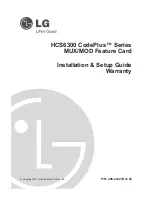
Fig 7 AKS 41 (Early Version) Internal Layout of Transmitter Housing and LED Function 


11.1. 

Measuring Test Voltage 

Connect a voltmeter to the pins provided to measure a voltage which is 
an expression of the ‘raw’ output signal measured directly from the 
capacitive rod. 

Two voltages are recorded during manufacture and recorded inside the 
transmitter housing. 

Voltage (x) at 0 %, i.e. when the rod is completely out of the liquid. 

Voltage (y) at 100 %, i.e. when the rod is completely immersed in 
the liquid. 

In a trouble-shooting situation, by measuring the voltage between the 
pins it is possible to determine whether the rod is defective.  If the 
measured voltage is within the two recorded values, the capacitive rod 
(outer tube, insulation, electrode and wiring connections) are in order. 

Green 

LED 

Red 

LED 

Two pins for 
calibration of 4 to 
20 mA signal 

Programming 
button (at 
bottom of tube) 

Two pins for measuring test voltage 

Summary of Contents for Danfoss AKS 41

Page 1: ...A 11 6 4 Signal Damping 11 6 5 Restore Factory Default Settings 12 7 Commissioning 12 8 Maintenance 12 9 Faults and Remedies 13 10 Spares 14 11 Appendix 1 AKS 41 Early Version 15 11 1 Measuring Test V...

Page 2: ...art of this publication may be reproduced or transmitted in any form or by any means electronic or mechanical including photocopying recording or by any information storage or retrieval system without...

Page 3: ...ls Part 1 1992 Specification for Presentation of Essential Information WARNING This denotes an immediate hazard with a high likelihood of personal injury or death if instructions including recommended...

Page 4: ...out the earlier version fitted with one green and one red LED can be found in Appendix 1 3 Operation The transmitter comprises consists of two parts an inner insulated electrode and an outer tube with...

Page 5: ...liquid level is registered as an increase in the rod s capacitance and hence results in a higher 4 to 20 mA output signal 4 Technical Data PARAMETER DETAILS General Enclosure IP 65 Max working press 1...

Page 6: ...HT MODEL INSERTION LENGTH B WEIGHT AKS 41U 6 152 mm 1 32 kg AKS 41 3 280 mm 1 7 kg AKS 41U 8 203 mm 1 41 kg AKS 41 5 500 mm 2 0 kg AKS 41U 12 305 mm 1 55 kg AKS 41 8 800 mm 2 4 kg AKS 41U 15 3 389 mm...

Page 7: ...Seal Outer Tube Plug can be mounted in four different positions Transmitter housing and tube can be separated without emptying the standpipe A B 1 BSP AKS 41 NPT AKS 41U Transmitter Housing Assembly...

Page 8: ...here is no voltage to the level transmitter Press the calibration push button and keep it depressed while refitting the connecting plug Release the push button the green LED is extinguished until the...

Page 9: ...ends 43 mm from the top gasket s contact face The liquid level transmitter has been factory calibrated to R717 ammonia so that the entire measuring range is utilised i e the transmitter s output sign...

Page 10: ...op of the rod measured from the gasket s contact face b Press the calibration push button and keep it depressed for approximately 5 seconds until the green LED stops flashing then release c Within the...

Page 11: ...n be measured b Bring the refrigerant liquid level to the desired maximum level c Press the calibration push button and keep it depressed for approximately 5 seconds until the green LED stops flashing...

Page 12: ...re Factory Default Settings To restore default settings press the calibration push button and keep it depressed for a minimum of 20 seconds until the green LED starts flashing Release the push button...

Page 13: ...e to gain access to the four screw terminals inside the plug where the four wires are connected Measure the resistance in the outer current loop between terminals 2 and 3 the plug must not be mounted...

Page 14: ...FAULT Output signal current is constant 4 mA Probable Cause Remedy Green LED flashing red LED also flashing early versions The transmitter is in setting mode Interrupt the supply voltage for about 10...

Page 15: ...t activated the green LED flashes When the programming button is activated the green LED follows the activation i e the green LED is On whenever the programming button is pressed Fig 7 AKS 41 Early Ve...

Page 16: ...arry out 12 2 step a first b Bring the liquid refrigerant to the level corresponding to the maximum limit of the measuring range i e the point on the rod where the transmitter s output signal is to be...

Page 17: ...16 75 mm A signal current of 6 mA therefore corresponds to a liquid level of 2 x 75 150 mm and a signal current of 12 x 75 900 mm As the liquid level can be adjusted between 100 and 950 mm it is poss...

Page 18: ...Danfoss AKS 41 Liquid Level Transmitter Publication 9 45 Section 9 Page 18 of 18 Issue 1 10 11 This page intentionally blank...

Reviews: