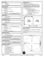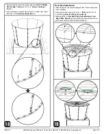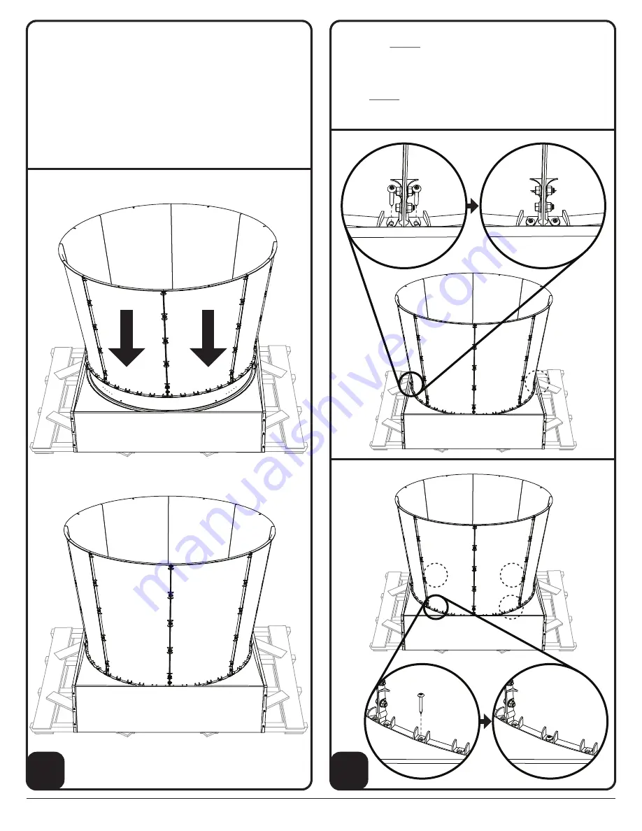
Cone Installation:
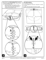
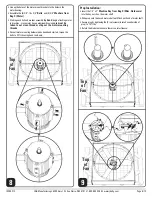
• Using (2) people lift the cone assembly onto the housing assembly.
— With J&D logoed cone sections facing the sides (not the top and
bottom) line up the edge of one of the cone pieces to the center
line of the housing.
— Make sure the raised part of the rubber gasket is inside the
cone assembly and not underneath it or crushed anywhere.
NOTE:
During the following process of securing the cone to the housing,
recheck the rubber gasket for proper placement and make adjust-
ments as needed
IS295-21C
J&D Manufacturing • 6200 Hwy 12 • Eau Claire, WI 54701 • 1-800-998-2398 • www.jdmfg.com
Page 9/13
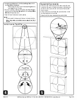
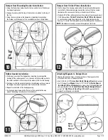
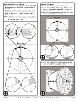
• Align the top and bottom of the cone at the areas of the damper door
bracket (see
Step 10
) and secure using the included
#3 Phillips Bit
from Bag 1 (Tools)
and
(4) #14-10 x 2”
Screws from Bag 5
(Part 1)
as shown below
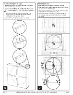
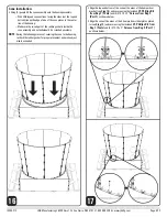
• Align the cone at the areas of the 4 damper door striker plates placed
in (see
Step 12
) and secure using the included
#3 Phillips Bit from
Bag 1 (Tools)
and
(4) #14-10 x 2”
Screws from Bag 5 (Part 1)
as shown below
16
17


