background image

10

10

GB - Getting Started

Make sure that all parts from the box content are included. Trans-
mitter, Car, Charger, Balancer, battery pack.

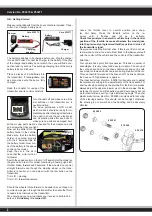
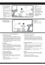
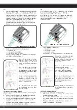
The battery pack has to be 
charged before use. Plug the 
charger into a 230V outlet. 
Connect the charger to the 
balancer and the balancer to 
the balancer plug of the bat-
tery The average charging 
time of the empty battery is 
about 5 - 7 hours.

Place 8 pieces of AA batteries into the 
transmitter. If rechargebale, please 
also make sure these are fully charged.

Read the chapter for usage of the 
transmitter and its controls carefully. 

Turn the radio off and make sure all the 
trim buttons on the transmitter are in 
neutral position.
You have purchased a RTR model, which 
means it should be ready for immedia-
te use after charging all batteries. You 
need to check the car, electronics and 
all plastic parts after each use to make 
sure no parts are damaged. 

Also all the 

moving parts must be checked for their clearance, bolts and 
screws that they are tight.

Now put the battery into the 
battery holder in the vehicle. 
Make sure that the battery 
holder is secured properly with 
the 2 included clips for the 
battery holder. Now connect 
the battery to the speed con-
trol in the model.
Keep the car in the air in case 
that the motor turns at full po-
wer.
Switch the speed control on the On / Off switch. Set the model on 
the ground and test it for proper functioning. Steering right/ left, 
throttle/ brake, forward and backward. If the wheels do not point 
straight forward even though the steering wheel on the transmitter 
is in neutral, you can adjust it with the trim button on the trans-
mitter.
Trim L/R = steering
Trim V/R = forward/backward

Should the wheels rotate forward or backward, even though no 
command was given through the transmitter, then also the throttle 
needs to be trimmed on the transmitter.
We encourage you now to activate your receiver‘s built-in Failsafe 
unit. 

On delivery it is turned off. 

Leave the throttle lever in neutral position (see chapter Fail Safe). Press 
the fail-safe button on the receiver until it flashes and let go to activate. 

Check this principle in an electric vehicle only in the neutral 
position of the throttle, because otherwise the model goes 
into the previously programmed throttle position in a loss of 
the transmitter signal.

Now you can make the first test drive. If this is your first rc car, we 
recommend to drive it on a small test track to familiarise yourself 
with the control of the vehicle and the controls of the transmitter. 

Attention! 

Your vehicle has a pivot front suspension. This has a number of 
advantages. It is very robust and easy to maintain. The set-up of the 
car has been done so the drive shaft will not pop out. As with any 
model, screws and bolts can losen during break-in of the car. This 
can result in tolerance of the drive shaft. The drive shaft can then 
pop out if high pressure is applied. 
The inner ball screw (item No.: 505081) will enable you to adjust 
the tolerance resulting in fine adjustments of the track width. For 
best results when setting up the pivot ball for the first time, please 
always adjust the upper and lower pivot in the same way. Fasten 
as far as the pivot can still be pulled up and down easyly but not 
as far that it will pop out if you give full steering angle. The outer 
plastic socket screw (item No.: 505080) is only used for securing of 
the steering knuckle. This should not be too tight, otherwise the 
steering is not smooth and the handling can be adversely affected.

Important!

By using LiPo batteries take care that  the undervoltage shutdown 
is activated, see page 20 - 23
Otherwise, your LiPo battery can be damaged by deep discharge. 
We recommend a cut-off voltage of 3 V per cell

10

Version No. 053275

ESC

On/Off

Battery

ESC/Battery
Connector

On/Off

L/R  F/B

Trim

50 5080

50 5081

07 9996

50 5079

Charger

Battery

Summary of Contents for 053270

Page 1: ...m h uber over 65 65 65 65 65 3 20 0 5 6 0 2 5 10 40 50 65 30 Km h K ub ub ber r r ov over v v 65 65 65 65 5 No 05 3275 3 15 0 0 4 0 2 5 10 25 30 40 20 Km h uber over 40 40 40 40 40 15 15 10 25 30 20 N...

Page 2: ...die dort beiliegen den Anweisungen schluss der Montagearbeiten erhitzten Teile fern halten I I J Sturm oder gar Gewitter d rfen Sie das Modell nicht betreiben setzungen entspricht und frei von Hinder...

Page 3: ...or thunder storms from obstacles transformer boxes or similar facilities This can result in radio interference causing loss of control over the model U I R U time can cause seriou accidents whether it...

Page 4: ...bauteile Fernsteuerung Ladeger t und Modell usw Bitte werfen Sie diese nur in die daf r vorgesehenen Sammelboxen bei den Kommunen Technische Daten Abmessungen 390 x 265 x 160 mm Gewicht 1650 g EP 175...

Page 5: ...ions 390 x 265 x 160 mm Weight 1650 g EP 1750 g BL Servos 1 x 4 5 kg Battery BL EP LiPo 7 4 V 3700 mAh NiMh 7 2 V 1800 mAh Motor EP BL Venti 540 270 W 3650 420 W 3200 KV No responsibility is taken for...

Page 6: ...t Bodychips 05 9273 Montagest nder mit Drehteller Car Stand rotatable 19 3130 Sto d mpfer St nder Shockstand 05 0590 O Hexagonal head wrench set 1 5 2 0 2 5 3 0mm 193065 Nabenbohrer f r Karosserie Hub...

Page 7: ...ge geben wurde versuchen Sie den Speedregler durch das aus trimmen des Gastrimmreglers am Sender in die Neutralstellung zu trimmen O O Failsafe Einheit zu aktivieren Im Auslieferzustand ist diese dea...

Page 8: ...d even though no command was given through the transmitter then also the thrott le needs to be trimmed on the transmitter We encourage you now to activate your receiver s built in Fail safe unit On de...

Page 9: ...ellung zu trimmen Wir empfehlen Ihnen nun die in Ihren Empf nger in tegrierte Failsafe Einheit zu aktivieren Im Auslieferzustand ist diese deaktiviert In dem Sie w hrend Sie den Gashebel am Sender in...

Page 10: ...trimmed on the transmitter We encourage you now to activate your receiver s built in Failsafe unit On delivery it is turned off Leavethethrottleleverinneutralposition seechapterFailSafe Press thefail...

Page 11: ...Kanaldoppelbe I Y I aber das Binden eines Empf ngers an den zugeh rigen Sender unbedingt notwendig Der 2 Kanal Sender ist f r die Lenkung und die Fahrfunktion mit hochwertigen Gebern ausgestattet Zum...

Page 12: ...it nicht einsetzen Beim Senderakku laden j 1 Legen Sie die Akkuzellen polrichtig ein 2 Stecken Sie das Ladeger t in eine Steckdose 3 Stecken Sie das Ladekabel in die Ladebuchse des Senders 4 Entfernen...

Page 13: ...ar transmitter can be quickly and simply programmed Both channels can be trimmed and the direction changed Fur U J and a red LED indicates the state of the battery charge 1 2 3 4 5 6 7 8 9 A B C D E R...

Page 14: ...w schalten den J I Empf nger G Schalten Sie nun den Sender aus Die Anlage ist beim n chs ten Einschalten gebunden I O les sehr genau OI Sie die Bindeprozedur kennzeichnet die einzelnen Elemente die be...

Page 15: ...mpf nger ein Die Signal LED leuchtet dauernd und zeigt an dass der Empf nger betriebsbereit ist c Bringen Sie den Gashebel am Sender in die Neutralposition O I d Dr cken Sie die Setup Taste am Empf ng...

Page 16: ...moved to the end of it s range Mit dieser Funktion werden die Vor und J schwindigkeit gesteuert Wenn der Steu ergeber nach hinten gezogen wird be wegt sich das Fahrzeug nach vorn wie auf dem nebensteh...

Page 17: ...shinweise 6 8 NiCd NiMH Zellen 2 LiPo Zellen x J abk hlen bevor Sie wieder starten _ I Empf nger ein beim Ausschalten gehen Sie in umgekehrter J I I keinesfalls in Schaumgummi oder hnlichem ein GB Con...

Page 18: ...unit Never wrap the ESC in foam we recommend mounting the unit to the vehicle using double sided sticky tape and that the switch is located where it will be pro tected but is also easily accessible Pl...

Page 19: ...ich der Speedregler nicht R I Die Abschaltung erfolgt bei ca 2 8V p Lipozelle 2S bzw 1V p Q Q I O J x ab Bereits bei der sp rbaren Leistungsreduzierung sollten Sie insbesondere bei der Verwendung von...

Page 20: ...rheitshinweise 6 8 NiCd NiMH Zellen 2 LiPo Zellen x J abk hlen bevor Sie wieder starten _ I Empf nger ein beim Ausschalten gehen Sie in umgekehrter J I I keinesfalls in Schaumgummi oder hnlichem ein G...

Page 21: ...ting the Receiver Battery Pack and Motor Connect the ESC the receiver the battery pack the steering servo and the motor together following the diagram below Ensure that you observe the correct polarit...

Page 22: ...malen Betriebsmodus haben die LED Signale j I Q leuchtet weder die rote noch die gr ne LED b Die rote LED leuchtet wenn das Fahrzeug sich vor oder r ckw rts bewegt Beim Bremsen blinkt die rote LED sch...

Page 23: ...Diese Funkton darf nicht deaktiviert werden 3 Fehlerhaftes Eingangssignal Sollte das Eingangssignal f r eine Zeitdauer von 0 2 Sek als nicht ordnungsgem erkannt werden wird der Motor abge schaltet 4...

Page 24: ...oor receiver signal f nger sowie das Empf ngeranschlusska J Check both the transmitter and receiver as well as the ESC connecting cable Der Motor hat die falsche Drehrichtung The motor turns in the wr...

Page 25: ...econds Programmierphase 1 Fahrmodus Program option 1 Drive mode Programmierphase 2 Bremsmodus Program option 2 Brake mode Programmierphase 3 R Program option 3 Low voltage cut off Taste dr cken Press...

Page 26: ...mse an Forwards brake on vor r ckw rts Bremse an forwards rever se brake on 2 Zugbremse Drag Brake Force 0 5 10 15 20 25 30 40 3 Unterspannung Low Voltage aus 2 6 V Zelle 2 6V cell 2 8 V Zelle 2 8V ce...

Page 27: ...hren eingestellt werden 7 Bremskraft min j O stellt werden wie stark die Bremse zu Beginn der Brems I O Wert wirksam wie bei Bremsst rke Punkt 2 GB be able to make the most of the various options they...

Page 28: ...lustration below This Zone can be set for both stick or pistol grip type transmitters as shown 9 j O a Brushless motor and you can set the timing here Please refer to you motor s instructions for the...

Page 29: ...cher oder Sand l schen Sicherheitsvorkehrungen J I I _ R mit den NiMh Zellen entstehen Bei unsachgem er Verwendung des Akkus kann dieser explodieren und oder brennen Es besteht Brand oder Ver tzungsge...

Page 30: ...or up to 30 minutes after the impact and for this observed for half an hour after any impact Burning cells or packs must be extinguished with sand or powder Safety Policy J or to its products which is...

Page 31: ...falt J _ R Lithium Polymer Zellen entstehen Bei unsachgem er Verwendung des Akkus besteht Brand oder Ver tzungsgefahr Y Y Zelle Vor mechanischer Belastung Quetschen Dr cken Biegen Bohren sch tzen Akku...

Page 32: ...precausions Because of the high power compactivity up to 150 Wh kg the cells are quite dangerous and need special care The company can occure when using the Lithium Polymer Cells indequate When using...

Page 33: ...g zu niedrig Akku laden bertemperaturabschaltung Speedregler abk hlen lassen Antriebswellen vorn fallen heraus zu gro e Spurbreite Spurbreite verringern GB Troubleshooting Problem Possible cause Solut...

Page 34: ...50 5024 50 5024 50 5023 50 5145 50 5078 50 5075 50 5071 50 5073 07 9989 50 5078 50 5075 50 5072 50 5071 50 5076 50 5071 50 5074 07 9989 50 5134 50 5156 50 5275 Montage vorderes Differential Front gea...

Page 35: ...07 9996 50 5084 50 5044 50 5040 50 5057 50 5054 50 5057 50 5028 50 5043 50 5054 07 9989 50 5028 50 5042 50 5040 07 9989 50 5084 50 5276 50 5041 50 5061 50 5079 50 5080 07 9996 Montage Achsschenkel vo...

Page 36: ...36 50 5133 Sto d mpfer Shock assembly Sto d mpfer Shock assembly...

Page 37: ...tzel BL Motor gear BL 50 5167 Motorritzel EP Motor gear EP 50 5036 50 5029 50 5101 Servo Saver Buffer assembly Montage Motor und Ritzel Motor assembly 13 0590 Motor EP 3 17 mm Motorwelle Shaft 13 0046...

Page 38: ...38 50 5030 50 5165 50 5341 50 5148 50 5026 50 5037 Zusammenbau vorne und hinten Front rear assembly Montage der Radio Platte Top plate assembly...

Page 39: ...39 50 5279 Cage assembly...

Page 40: ...40 50 5116 schwarz black 50 5280 rot red Zusammenbau vorne und hinten Front rear assembly...

Page 41: ...j toe in toe out A j and the vehicle tends to oversteer but it has better directional stability B j but has a worse directional stability Negative camber positive camber front and rear A Q j Better gr...

Page 42: ...heit und tieferer Fahrzeugschwerpunkt j mehr Bodenfreiheit und h herer Fahrzeugschwerpunkt GB Suspension Settings Front caster high low x j x provides a better steering on corner entries j but can res...

Page 43: ...weniger oder mehr Clip Federvorspannung weniger oder mehr Clips Spring tension less or more clip D mpferwinkel hinten oben D mpferwinkel Shock angle Sturz hinten Spur vorne Track front Nachlauf Track...

Page 44: ...gspunkte GB Setting points Federvorspannung Spring tension Federvorspannung Spring tension D mpferwinkel Shock angle D mpferwinkel Shock angle D mpferwinkel Shock angle Sturz nur innere Schraube Cambe...

Page 45: ...45 45 DE Einstellungspunkte GB Setting points Federvorspannung Spring tension O Suspension travel socket screw D mpferwinkel Shock angle Sturz hinten J D mpferwinkel Shock angle...

Page 46: ...No 50 5101 Chassis Chassis No 50 5036 Spurstange Steering connecting set No 50 5024 Getriebewelle J No 13 0590 E Motor m 3 17mm Welle E Motor with 3 17mm shaft No 50 5028 Querlenkerbolzen unten innen...

Page 47: ...f Differential bevel gear set No 50 5075 Getriebegeh use Gear box set No 50 5041 Querlenker oben vorne Front upper suspension set No 50 5133 Sto d mpfer Shocks No 50 5116 1 10 schwarz black J J No 50...

Page 48: ...ube Connter sunk screw No 50 5053 M3 6 Gewindeschraube Connter sunk screw No 50 5081 Pivot Kugelkopfschrauben Ball head screw set No 50 5131 Querlenkerstift Set No 50 5277 Antriebswelle hinten Drivesh...

Page 49: ...be No 50 5059 M3 10 Madenschraube Set screw No 50 5285 Empf ngerbox J DE Ersatzteile GB Spare parts Kein Bild no picture No 50 5155 Differential vo hi komplett Diff set front rear No 505283 Dekorbogen...

Page 50: ...No 50 5378 Tuning Alu Querl unten hinten Control arm lower back No 07 4416 High End 9712 MG Servo Servo No 50 5182 Wheelybar Wheelyba No 50 5365 Tuning Alu Querl oben vorn Control arm top front No 13...

Page 51: ...lb ist es auch wichtig bei Lipo s die R O he Anleitung da der Akku sonst Schaden nimmt The running time of your model see diagram above depends on the capacity of your battery in mAh The average runni...

Page 52: ...o jamara com www jamara com Reitter Modellbau Versand Schwanenberg 8 72519 Veringendorf Ij j j I www modellbauversand de I_ I Extra Trade Lindenstra e 82 66787 Wadgassen Ij j j I www extra trade de D...

Reviews: