Version: 3.1.0
55
Unplug the cable connecting the sensor to the TIO at the robot end → power off the robot and the CAB →
plug the cable connecting the sensor to the TIO at the robot end → turn on the CAB → redo the
configurations. If the problem persists after restarting, please contact us. Any unauthorized attempt to
disassemble and repair the sensor, robot, CAB or cable is NOT allowed.
Note 2: If you've chosen the TIO channel for the current torque sensor, switching to the TIO's RS485
channel configuration or pin configuration while communicating will trigger an error message. At this time,
turn off the sensor and try again.
Figure 3-7 Se System Configuration Interface (TIO Type)
g.
Open the "Manual operation" page, tap [Configure], check [Do not initialize], tap [confirm], and close
the page. Then tap the [View] button on the right, turn on all the toggle switches (Fx, Fy, Fz, Mx, My,
Mz, and real-time. If it is a 1D sensor, turn on the toggle switch of Fz). Slightly push or pull the sensor. If
the graph fluctuates, the sensor communication is normal (See the usage of the real-time display of
external force function for details);
h.
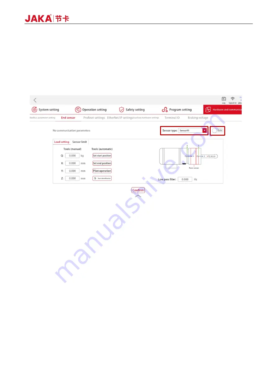
After normal sensor communication is established, set the load parameters: Tap [Settings] →
[Hardware and communication] → [End sensor] → [Load setting], and tap the input box under the
[Tools (manual)] bar on the left to manually input the mass and centroid position of the end tool
connected to the sensor, or use the auto load identification function (See the "Usage of JAKA Zu Se"
section for details. 1D sensor does not support auto load identification). Once the load identification
data has been verified (or after manually entering the load data), tap the toggle switch at the upper right
of the interface to change its status from [Run] to [Edit], and tap the [Confirm] button at the bottom of
the interface. After "Setting succeeded" pops up, tap the toggle switch at the upper right of the interface
again to change its status from [Edit] to [Run]. At this point, the sensor is basically set up;
Summary of Contents for Zu Series
Page 1: ...JAKA ROBOTICS Force Control Products JAKA Se and JAKA Sp...
Page 3: ......
Page 4: ......
Page 17: ...Version 3 1 0 13 M3 2 0 M4 4 0 M5 8 0 M6 13 0 M8 35 0...
Page 41: ...Version 3 1 0 37 Figure 2 36 Installation and Dimensions of the Force Sensor Indicator light...
Page 61: ...Version 3 1 0 57 Figure 3 8 Force Display Interface of the App...
Page 75: ...Version 3 1 0 71 Figure 3 19 Force Display Interface of the App...
Page 79: ...Version 3 1 0 75 Figure 3 21 Collision Detection Function Settings of JAKA Zu Sp...


