CV-M9 CL
6.2.4. Partial Scanning
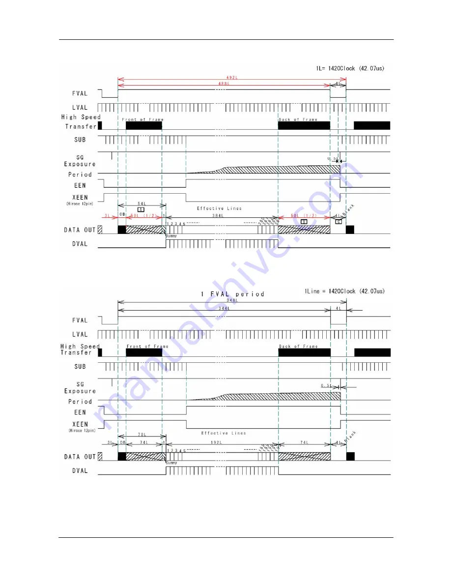
1L = 42.07
µ
s
Fig. 16 Vertical timing for 1/2 partial scan
Fig. 17 Vertical timing for 1/4 partial scan
- 12 -
Page 1: ...Digital 3CCD Progressive Scan RGB Color Camera CV M 9CL Operation Manual Camera Revision A Manual Version 1 3 M9Clmanuver13 doc JPT 21 09 05 ...
Page 2: ...rnal trigger 14 6 3 2 Output of EEN 14 6 4 Operation Modes 15 6 4 1 LVAL synchronous accumulation 16 6 4 2 LVAL a synchronous accumulation 17 6 4 3 Continuous operation 18 6 4 4 Edge Pre select Trigger Mode 19 6 4 5 Pulse Width Control Trigger Mode 20 6 4 6 Reset Continuous Trigger mode 21 6 4 7 Sensor Gate Control 22 6 5 Other Functions 23 6 5 1 Customized shading correction 26 6 6 Request Functi...
Page 3: ...ributor 2 Standard Composition The standard camera composition consists of the camera main body and tripod mount plate The camera is available in the following version CV M9CL 3 CCD progressive scan color camera 3 Main Features 3 x 1 3 CCD Progressive Scan RGB Color Camera for vision applications 3 x 1034 h x 779 v 4 65 µm effective square pixels Compact RGB prism for C mount lenses Chromatic shad...
Page 4: ... sensors 3 Camera Link base connector 1 4 Camera Link medium connector 2 5 12 pin connector for DC 12V power external sync signals 6 LED for power and trigger indication 7 Switch for 1 push white balance 8 Mounting holes 8 x M3deept5 1 Note Rear protrusion on C mount lens must be less than 4 0mm Fig 1 Locations 3 ...
Page 5: ... Link standardized multiplexed signal output interface Camera Link base configuration is used for 3 x 8 bit RGB signal The interface circuit is build around the NS type DS90CR285MTD The following signals are found on the Digital Output Connector SerTC RXD serial data to camera SW301 1 Off for CL On for HR SerTFG TXD serial data to frame grabber SW301 1 Off for CL On for HR CC1 Trigger input TI 0 f...
Page 6: ...flop which is toggled by the negative or positive differentiated spikes caused by the falling or rising trigger edges GND 5V 15k TTL 1k GND 100n 1k 68k 100k 1n 75Ω Trig input pin 10 SW301 2 GND 5V 15k TTL 1k GND 100n 1k 68k 100k 1n 75Ω Trig input pin 10 SW301 2 The trigger polarity can be changed by TP 1 Trigger input level 4 V 2 V It can be terminated by SW301 2 ON for 75Ω OFF for TTL The trigger...
Page 7: ...Pair 5 Pair 4 Pair 7 Pair 6 Pair 8 Pair 9 Pair 10 Pair 11 Sheilds TXD out RXD in Ext trig 1 in Ground Signal Connector pin CV A33 Camera Camera Link Cable Camera Signals To Frame Grabber Ext Trig 2 in Camera Link Pin 1 14 13 26 X0 X1 X2 X3 Xclk SerTFG SerTC CC1 CC2 CC3 CC4 Sheilds 4 x 7 1 MUX 8bit 10bit D2 D0 D3 D1 D4 D2 D5 D3 D6 D4 D7 D5 D8 D6 D9 D7 NC D8 NC D9 NC NC NC NC NC NC NC NC NC NC NC NC...
Page 8: ...7 Port A7 Tx5 NC Port D7 Tx5 G D0 Port B0 Tx7 R D8 Port B0 Tx7 G D0 Port E0 Tx7 G D1 Port B1 Tx8 R D9 Port B1 Tx8 G D1 Port E1 Tx8 G D2 Port B2 Tx9 NC Port B2 Tx9 G D2 Port E2 Tx9 G D3 Port B3 Tx12 NC Port B3 Tx12 G D3 Port E3 Tx12 G D4 Port B4 Tx13 B D8 Port B4 Tx13 G D4 Port E4 Tx13 G D5 Port B5 Tx14 B D9 Port B5 Tx14 G D5 Port E5 Tx14 G D6 Port B6 Tx10 NC Port B6 Tx10 G D6 Port E6 Tx10 G D7 Por...
Page 9: ... shading for lens vignetting and for CCD shading It makes the choice of lenses wider The camera with a given lens and a given f number is looking on a homogeneous white scene A horizontal profile of the shading in 128 points is made for the 3 colors A vertical profile of the shading in 96 points is made for the 3 colors The result is stored as gain difference from the image centre Data from this h...
Page 10: ... video output S l o p e 2 0 0 32 890 1023 2848 LSB Slope 1 4095 100 Knee adjust range 102 Slope 0 Slope adust range 12 bit CCD signal The knee function is individual RGB Slope 0 S l o p e 2 The new slope can be set from 1 0 to 1 2 A slope 1 0 is a clipper function which will limit the output signal A slope 1 2 will function as a 2 times contrast expanding function The slope parameter range is from...
Page 11: ...tical centred scanned area on the CCD sensor The front and back lines are the lines used for the fast dump readout used in partial scanning Scanning Start line End line Active lines Front lines Back lines Blank lines Remarks SC 0 Full 1 768 768 12 8 4 Refer to fig 15 SC 1 1 2 192 576 384 54 50 4 Refer to fig 16 SC 2 1 4 288 480 192 78 74 4 Refer to fig 17 SC 3 1 8 336 432 96 90 86 4 Refer to fig 1...
Page 12: ...CV M9 CL 6 2 2 Horizontal timing Fig 14 Horizontal timing 6 2 3 Vertical timing 1L 42 07 µs Fig 15 Vertical timing for full scan 11 ...
Page 13: ...CV M9 CL 6 2 4 Partial Scanning 1L 42 07 µs Fig 16 Vertical timing for 1 2 partial scan 1L 42 07 µs Fig 17 Vertical timing for 1 4 partial scan 12 ...
Page 14: ...CV M9 CL Fig 18 Vertical timing for 1 8 partial scan 6 2 5 Vertical binning Fig 19 Horizontal timing for V binning 13 ...
Page 15: ... the 12 pin connector pin 10 TI 1 Here it should be 4 0 Vp p 2 0 V from a 75 Ω source The trigger input signal can be 75 Ω terminated Factory setting is TTL For 75 Ω termination SW301 2 should be ON 6 3 2 Output of EEN XEEN The Exposure Enable signal EEN indicate that the accumulation is ongoing It can be used for controlling a strobe flash The XEEN signal is found on the 12 pin connector pin 9 It...
Page 16: ...ximum frame rate in trigger modes can then be close to the frame rate in continuous mode The minimum trigger interval should be longer than 1 FVAL 2 LVAL To avoid 1L time jitter in LVAL synchronous mode it is recommended to synchronize the trigger to LVAL In LVAL a synchronous accumulation a new trigger must not be applied before the previous frame is read out FVAL is low The minimum trigger inter...
Page 17: ...gger trailing edge It results in up to 1 LVAL jitter In trigger modes with LVAL synchronous accumulation a new exposure can be started while the previous frame is read out The new exposure should not finish before the frame is read out FVAL shall be low for 2 LVAL The maximum frame rate in trigger modes can then be close to the frame rate in continuous mode Minimum trigger interval 1 FVAL 2 LVAL I...
Page 18: ...r time in number of LVAL In PWC mode the exposure stops 0 5 L after the trigger trailing edge A new trigger must not be applied before the previous frame is read out FVAL is low Minimum trigger interval exposure time 1 FVAL 3 LVAL Important notes on using this mode In LVAL a synchronous PWC mode there is no exposure jitter Fig 23 LVAL a synchronous accumulation in EPS mode Fig 24 LVAL a synchronou...
Page 19: ...rolled iris For timing details refer to fig 13 through fig 20 To use this mode Set function Trigger mode to Continuous TR 0 Scanning SC 0 through 3 Vertical binning BI 0 BI 1 Shutter mode normal programmable SM 0 through 2 Shutter speed SH 0 through 11 Programmable exp PE 0 through 791 Other functions and settings Input Important notes on using this mode For timing details refer to fig 13 through ...
Page 20: ...de to Edge pre select TR 1 Scanning SC 0 through 3 Vertical binning BI 0 BI 1 Shutter mode to normal or programmable SM 0 through 2 Shutter speed SH 0 through 11 Programmable exp PE 0 through 791 Accumulation LVAL synch or a synch LS 0 LS 1 Other functions and settings Input Ext trigger Camera Link or 12 HiRose TI 0 TI 1 Important notes on using this mode Trigger pulse 2 LVAL to 1 FVAL To avoid 1 ...
Page 21: ...rough fig 20 and fig 26 To use this mode Set function Trigger mode to Pulse width control TR 2 Scanning SC 0 through 3 Vertical binning BI 0 BI 1 Accumulation LVAL synch or a synch LS 0 LS 1 Other functions and settings Input Ext trigger Camera Link or 12 HiRose TI 0 TI 1 Important notes on using this mode Trigger pulse width 2 LVAL to 1 seconds To avoid 1 LVAL jitter in synch accum synchronize th...
Page 22: ...tails refer to fig 13 through fig 20 and fig 27 To use this mode Set function Trigger mode to Reset continuous trigger TR 4 Scanning SC 0 through 3 Vertical binning BI 0 BI 1 Shutter mode normal programmable or auto SM 0 through 2 Shutter speed SH 0 through 11 Programmable exp PE 0 through 791 Accumulation LVAL synch or a synch LS 0 LS 1 Other functions and settings Input Ext trigger Camera Link o...
Page 23: ... internal SG pulse the sensor gate control signal should be low 2 µs before Fig 29 shows the sensor gate signal setup time and hold time It is inside the first line after FVAL goes low For timing details refer to fig 13 through fig 20 and fig 28 29 To use this mode Set function Trigger mode to Sensor gate control TR 3 Scanning SC 0 Vertical binning BI 0 Other functions and settings Input Ext SG co...
Page 24: ...I 1 Binning mode is a function where the signal charge from 2 or more adjacent pixels are added together and read out as one pixel A resulting full frame with lower spatial resolution can be read out with a higher rate and higher sensitivity The CV M9CL has vertical binning 2 1 Vertical binning is done by adding the pixel charge from adjacent lines together in the horizontal ccd register It is don...
Page 25: ...tion can be requested by the command AWRS lower right lower middle lower left middle right middle middle left upper right upper middle upper left lower right lower middle lower left middle right middle middle left upper right upper middle upper left Full Full 0 1 2 3 4 5 6 7 8 9 Set Auto White Balance area WA This function makes it possible to set the one push white balance sensing area to the are...
Page 26: ...Knee slope blue KSB 0 through KSB 4095 Shading Mode SDM 0 SDM 1 If the command SDM 1 is received the shading corrector is enabled This corrector will compensate for the color shading caused by the prism for the circular shading caused by the lens vignetting and for CCD sensor shading The parameters for shading corrections are factory loaded with a given lens and f number For details refer to 6 1 1...
Page 27: ...he real setup The camera setting has to be as follows Master gain 0dB Individual gain 0dB Shutter off Trigger modes off use Normal mode Binning and Partial scan off Use 10 bit output mode Shading corrector off Continue with the following Set up the illumination as it should be in the real application Place a perfectly flat white object piece of paper at the actual scene No reflections must be visi...
Page 28: ...anufacturing code Model Name MD If received the camera will send back its model name User ID UD With this command the user can program and store up to 16 characters for identification Change RS232C Baud Rate BDRT 0 through BDRT 2 It is possible to change the communication speed from the normal 9600 Baud to a higher value BDRT 0 is 9600 BDRT 1 is 19200 and BDRT 2 is 38400 bps The new speed will be ...
Page 29: ...0 off 1 on LS lval synchronous accumulation 0 sync 1 async RF rct fval type 0 cameralink 1 JAI standard TI trigger input 0 camera link 1 hirose 12pin TP trigger polarity 0 active low 1 active high SC scanning format 0 full frame 1 1 2 partial 1 1 4 partial 1 1 8 partial BI binning 0 binning off 1 v binning BA output bit allocation 0 10bit 1 8bit CBAR color bar 0 off 1 on WB white balance 0 manual ...
Page 30: ...utton To access the switch Remove the top cover frame 6 screws Remove the bottom cover frame 6 screws Remove left side cover Seen from rear 5 screws SW 301 is seen on the rear board behind the LED and WB button No Functions OFF ON 1 Communication port switch LVDS Camera Link RS232C HIROSE 12pin 2 Trigger In Termination switch TTL 75Ω Factory settings are shown in Bold Italic Fig 34 Switch position...
Page 31: ...S 8 CTS 9 CI 9 pin D con PC COM PORT CAMERA Protocol Transmit setting to camera NN Parameter CR LF NN is any kind of command Capital or small letters The camera answers COMPLETE CR LF Note Some commands can only be requested To have all communication visible on the emulator screen start with EB 1 CR LF The camera answers COMPLETE CR LF Transmit request command to camera NN CR LF NN is any kind of ...
Page 32: ...dard TI Trigger Input TI Param CR LF 0 CamerLink 1 12 pin Hirorose TP Trigger polarity TP Param CR LF 0 active low 1 active high E Gain and analogue signals setting WB White Balance WB Param CR LF 0 Manual One Push 1 Continuous AWB 2 3200K 3 4600K 4 5600K AW One Push White balance AW Param CR LF 0 one push auto white balance When WB 0 WA Set Auto White Area WA Param CR LF 0 Full 1 UL 2 UM 3 UR 4 M...
Page 33: ...more than a program with a window interface It also provides an easy and efficient ActiveX interface built for MS Windows 98 ME NT and 2000 The OCX interface has the ability to connect to the camera using the serial interface of the PC by reading and writing properties for the camera This integration requires simple programming skills within Visual Basic Visual C or similar languages in a Microsof...
Page 34: ...above and it will automatically be included in the list of help files For newer camera models the About Window also shows Model Name camera ID and User ID It is possible to edit and save free text in User ID At the bottom of the windows all windows but the Communication Window is a coloured bar The bar is green when the Camera Control Tool is connected to a camera and the camera is turned on The b...
Page 35: ...ached and all functions are fully functional in offline mode Off line mode is indicated in The Communication Window where a status field with graphic and text indicates the on off line status Changing the selected communication port from the communication window changes the online off line status If a camera is found on the selected communication port the application runs online otherwise offline ...
Page 36: ...ra Control Tool bar is always on top of other windows 2 When you minimize the Camera Control Tool bar all open windows will close 3 It is possible to work with the Camera Control Tool when the camera is online and when the camera is offline 4 The newer JAI cameras always start up with the last used user area but for some old models it will start up with the last saved user area 5 The Camera Contro...
Page 37: ...tline 10 Specifications 10 1 Spectral sensitivity The shown responses are for prism and CCD sensors combined Wave length nm 400 500 600 700 800 1 0 0 8 0 6 0 4 0 2 0 0 Relative response B G R Wave length nm 400 500 600 700 800 1 0 0 8 0 6 0 4 0 2 0 0 Relative response B G R Fig 38 Spectral sensitivity for CV M9CL 36 ...
Page 38: ...B Synchronization Int X tal or random trigger Inputs TTL Camera Link Ext trigger 4 Vpp 2 V TTL or 75 Ω Ext trigger Outputs TTL Camera Link EEN output 4 Vpp from 75 Ω source RGB 8 10 bit video output D0 D9 Pixel clock DVAL LVAL FVAL and EEN Control interface TXD and RXD via RS232C serTC and serTFG via Camera Link Trigger modes Continuous Edge Pre Select Pulse Width Control Reset Continuous Trigger ...
Page 39: ...ng any modification such as changes of jumper and switch setting 11 2 Typical Sensor Characteristics The following effects may be observed on the video monitor screen They do not indicate any fault of the camera but do associate with typical sensor characteristics V Aliasing When the CCD camera captures stripes straight lines or similar sharp patterns jagged image on the monitor may appear Blemish...
Page 40: ... Company and product names mentioned in this manual are trademarks or registered trademarks of their respective owners JAI A S cannot be held responsible for any technical or typographical errors and reserves the right to make changes to products and documentation without prior notification JAI A S Denmark Phone 45 4457 8888 Fax 45 4491 8880 www jai com JAI Corporation Japan Phone 81 45 440 0154 F...