ADwin-Pro
Hardware, manual version 2.9, June 2006
85
Pro I: Analog Output Modules
Pro-AOut-4/16 Rev. B, Pro-AOut-8/16 Rev. B
ADwin
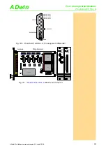
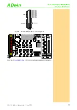
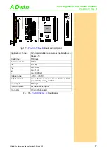
Fig. 153 – Pro-AOut-8/16 Rev. B: Board and front panel
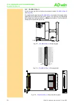
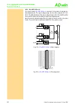
Figure
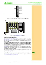
illustrates all possible DIL switch positions. The "x" in the DIL switch
title stands for the number of the corresponding DAC (see
). The
adjustment of gain and offset is made by software (see
).
If nothing else has been specified upon ordering the module, the voltage range
is set to ±10V. Each time you change the DIL switch settings you have to reca-
librate the ADC, in order to assure good measurement results.
19DA0101
A0 A1 A2 A3 A4 A5 A6 A7
DC/DC-converter
74LS19
ON
DIP
1
2
3
4
5
6
7
8
OP
A
2132
OP
A
2132
A
D
588B
Q
OP
A
2132
OP
A
2132
OP
A
2132
OP
A
2132
LT
1468
LT
C
1597-
1A
DS
1867
LT
1468
LT
1468
LT
C
1597-
1A
DS
1867
LT
1468
LT
1468
LT
C
1597-
1A
DS
1867
LT
1468
LT
1468
LT
C
1597-
1A
DS
1867
LT
1468
LT
1468
LT
C
1597-
1A
DS
1867
LT
1468
LT
1468
LT
C
1597-
1A
DS
1867
LT
1468
LT
1468
LT
C
1597-
1A
DS
1867
LT
1468
LT
1468
LT
C
1597-
1A
DS
1867
LT
1468
Actel
A42MX16
1
3
5
7
2
4
6
8
10V
5V
BIP
UNI
AOUT8/16
ANALOG
OUTPUT
1
2
3
4
5
6
7
8
AOUT8/16
ANALOG
OUTPUT
Voltage range
DILx1
DILx2
±5V bipolar
5V
BIP
±10V bipolar (default)
10V
BIP
0…5V unipolar
5V
UNI
0…10V unipolar
10V
UNI
Fig. 154 –
Pro-AOut-4/16 Rev. B, Pro-AOut-8/16 Rev. B
: DIL switch settings
for the output voltage range


