Pro II: Analog Output Modules
Pro II-AOut-4/16 Rev. E
ADwin
34
ADwin-Pro
Hardware, manual version 2.9, June 2006
5.4.1 Pro II-AOut-4/16 Rev. E
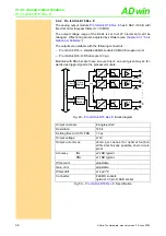
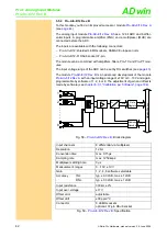
has 4 DAC (16 bit) with
fixed 1st order low-pass filters (fc = 10MHz).
The output voltage range of the DACs is set to ±10V bipolar and can’t be
changed. Offset and gain are adjusted by software (see
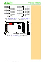
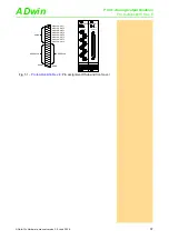
The outputs are available with the following connectors:
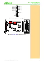
– Pro II-AOut-4/16-L: shielded LEMO-sockets CAMAC European norm.
– Pro II-AOut-4/16-D: DSub socket 37-pin.
Modules with DSub socket have an event input; an event given may be for-
warded as trigger signal to the processor module.
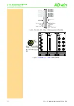
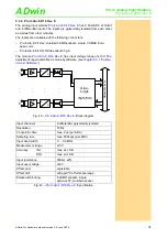
Fig. 46 –
: Block diagram
Output channels
4 single-ended
Resolution
16 bit
Settling time to 0.01% FSR
< 3µs
Output voltage
±10V
Output current max.
±5 mA per channel for optimal function
±35mA technically possible, short-circuit-
proof
Accuracy
INL
±2 LSB typical
DNL
±1 LSB typical
Offset error
adjustable
Gain error
adjustable
Offset drift
±10 µV/ºC
Connector
4 LEMO sockets
optional: 37-pin D-SUB socket
Fig. 47 –
: Specification
2
AD
w
in
-P
ro
I
I
bu
s
Addr.
Data
Data
Register
Address
Decoder
InAmp
+
-
D
A
1
3
4
LPF
InAmp
+
-
LPF
InAmp
+
-
LPF
InAmp
+
-
LPF
D
A
D
A
D
A
Data
AGND
AGND
AGND
AGND

