background image

V03 

JCAII   

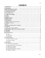
CONTENTS 

1. Introduction


 ......................................................................................................... 1

2. Precautions


 .......................................................................................................... 1

3. Before Using the Product


 ................................................................................... 1

3-1 Unpacking and Checking


 ......................................................................................................... 1

3-2 Installing Components


 ............................................................................................................. 1

3-3 Leveling the Scale


 .................................................................................................................... 1

4. Product Introduction


 ........................................................................................... 2

4-1 Display


 ....................................................................................................................................... 2

4-2 Keypad


 ...................................................................................................................................... 3

5. Analog Section


 .................................................................................................... 4

6. Setting mode


 ........................................................................................................ 4

7. Dual Channel


 ....................................................................................................... 5

7-1 Diagram of sub channel connector


 ........................................................................................ 5

7-2 Installation Process


 .................................................................................................................. 5

7-3 Setup


 ......................................................................................................................................... 6

7-4 Maximum Capacity & Division Setting


 ................................................................................... 6

7-5 Calibration


 ................................................................................................................................. 7

7-6 Set AD gain of remote platform


 ............................................................................................... 8

7-7 Switch between Main scale and Remote platform


 ................................................................. 8

8. Operation


 ............................................................................................................. 8

8-1 Zero-point


 .................................................................................................................................. 8

8-2Tare & Preset Tare


 ..................................................................................................................... 8

8-2-1Tare


 ................................................................................................................................... 8

8-2-2Preset Tare


 ........................................................................................................................ 9

8-2-3 Auto-tare


 .......................................................................................................................... 9

8-3 Counting method


 .................................................................................................................... 10

8-3-1Key in a known unit value


 ............................................................................................... 10

8-3-2 Sample counting


 ............................................................................................................ 10

8-3-3 ACAI


 ................................................................................................................................ 11

8-4 Accumulation


 ........................................................................................................................... 11

8-4-1Choose Accumulation Mode


 ............................................................................................ 11

8-4-2Set the Max Account of accumulation


 .............................................................................. 11

8-4-3Manual Accumulation


 ...................................................................................................... 12

8-4-4Accumulation display


 ...................................................................................................... 12

8-4-5Print while display of accumulation


 ................................................................................. 13

8-4-6Delete accumulation


 ........................................................................................................ 13


Summary of Contents for JCAII

Page 1: ...Capacity Division Setting 6 7 5 Calibration 7 7 6 Set AD gain of remote platform 8 7 7 Switch between Main scale and Remote platform 8 8 Operation 8 8 1 Zero point 8 8 2Tare Preset Tare 8 8 2 1Tare 8...

Page 2: ...8 7 2Set the low limit of quantity 15 8 7 3Enable Disable the quantity limit function 15 8 8 Weight checking 16 8 8 1Set the high limit of weight checking 16 8 8 2Set the low limit of weight 16 8 8 3...

Page 3: ...ce shoul d be perf orm ed by aut hori zed personnelonl y 3 Before Using the Product 3 1 Unpacking and Checking Open the package and check the instrument for transport damage Immediately inform your de...

Page 4: ...ue entered via numeric keys 7 Under the sample counting mode Symbol points at SMPL when calculated unit weight is lower than 4 5 of scale division or the quantity of sample is less than 10 pieces 8 Ac...

Page 5: ...r tare unit weight and other data entries Key can be also as a space key when edit label Decimal point Initiates function setting Sets the weight to zero Clears the indicated input values Displays gro...

Page 6: ...lay output function under HI LO setting Print Disable switch off relay output function under HI LO setting 5 Analog Section Input sensitivity 1 4mV V Zero adj Range 20 FS A D conversion rate 10 times...

Page 7: ...ep sound default in when check is OK when check is Hi Lo using scale s buzzer when check is OK when check is Hi Lo using light tower s buzzer 5 P 04 ACAI default off Options off 5 10 15 20 25 30 35 40...

Page 8: ...rm only Use the main scale only 5 Press key to save the setting and return to weighing mode 7 4 Maximum Capacity Division Setting 1 Press and hold while turning on the scale Do not release till is dis...

Page 9: ...rm Here take JCAII 6K as an example 1 Press key and hold while turning on the scale Do not release till is displayed in the Unit Weight window 2 Press key to start the zero point calibration and wait...

Page 10: ...AD gain Options 1 2 4 8 16 32 64 5 Press to save and return to normal weighing mode 7 7 Switch between Main scale and Remote platform Press to switch between main scale mode and sub channel mode remot...

Page 11: ...s with a symbol pointing at NET and another pointing at PRESET TARE 3 Put the load on the container The display shown is the Net weight Press key to see the Gross weight 5 To clear tare with an empty...

Page 12: ...then press key 2 Put the article on the pan and the scale starts counting Note Symbol points at UW when entered unit weight is lower than 4 5 of scale division Unit weight is too small for ensuring a...

Page 13: ...rameter P4 to OFF it means that the scale will do the ACAI in all situations If you set the average parameter to 15 the scale will not work if there is an object shortage or more than 15 of the unit w...

Page 14: ...to warm Press twice to delete all accumulation 8 4 3 Manual Accumulation 1 Put the article on the pan Press key The symbol is blinking in the Unit Weighting window This is the first accumulation 2 The...

Page 15: ...normal weighing mode Delete total accumulation 1 Enter the total accumulation display press to delete 2 Press again to delete and return to normal weighing mode If you don t want to delete press to r...

Page 16: ...et Serial Number Mode 1 Under normal weighing mode press It will shown as If not press 2 Press or to choose the serial number mode No action The serial no plus 1 when symbol appear The serial no plus...

Page 17: ...7 1 Set the high limit of quantity 1 Press under normal weighing mode The last high limit value of quantity is blinking in the Total Count window while the arrow is pointing at HI If not press Eg 111...

Page 18: ...high limit of weight you want 3 Press to save and return 8 8 2Set the low limit of weight 1 Press under normal weighing mode The display of the weight is blinking in the Weight window while the arrow...

Page 19: ...mber and the Total Count window will blinking 3 Press to save 8 9 2Saving ID method 2 For example there is a unit weight 1 23g already existing and save it to ID 12 1 Press and key in the accumulation...

Page 20: ...or do nothing for a while to edit the next character Press to move leftwards and to move rightwards 4 Repeat 2 3 steps to complete the first 16 characters 5 Press to complete the next 16 characters T...

Page 21: ...oad the printer format before HI LO checking do not work Make sure the function is enabled The value of LO is greater than HI No sound in HI LO checking function Make sure the parameter P 03 is set co...

Page 22: ...versal 9 pin male to 9 pin male RS 232 connecting cable Scale to PC 1 Connect the scale and computer by using the RS232 cable as the following picture 2 Please set the print mode Manual Print after ap...

Page 23: ...d Option application Remark AP1 Can print out bar code BP AP2 2009 05 27 14 46 38 G W 1 000kg U W 0 5g Total 400PCS Zebra AP3 EZ godex AP4 Can print out accumulation data SH 24 AP5 Only the weighing d...

Page 24: ...V03 JCAII 22 AP6 Light tower can indicate three different situation LED Light Tower...

Page 25: ...V03 JCAII 23 Two optional devices being used Option Application AP1 BP Or ZEBRA Or GODEX Or LED Light Tower Or PC LED Display...

Page 26: ...V03 JCAII 24 AP2 BP Or ZEBRA Or GODEX Or PC...

Page 27: ...V03 JCAII 25 Three optional devices being used Option Application AP1 BP Or ZEBRA Or GODEX Or PC LED Display And LED Light Tower 10 Relay Module Diagram RELAY OUTPUT Alarm CO M N C N O...

Page 28: ...V03 JCAII 26 HI CO M N C N O OK CO M N C N O LO CO M N C N O RELAY CONTACT SPEC 1A 24VDC 0 5A 125VAC 0 25A 250VDC...

Reviews: