background image

PR-805/810/810

User Manual


71


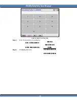
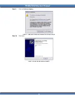
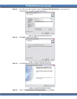
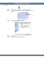
Step 2)


Click on the 

icon

.


Step 3)


Click 

Run.


Step 4)


Click 

Browse


B

LUETOOTH

* (

OPTIONAL

)


 

HOST (PC) 

PR-8XX


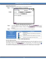
FIGURE 76: BLUETOOTH TOPOLOGY.


The  optional  Bluetooth  feature  allows  the  PR-8XX  to  be  wirelessly  controlled  by  a  remote  host  using 
Remote Mode commands from a user developed application or terminal emulator such as HyperTerminal 
or  PhotoWin  control  software  up  to  100  meters

1  

away.   When  installed,  the  supplied  driver  creates  a 

virtual RS-232 port that operates like a traditional port with respect to programming. 

I

NSTALLING THE 

(P

HOTO 

R

ESEARCH SUPPLIED

) B

LUETOOTH 

A

DAPTER 

D

RIVER ON 

H

OST


The USB Bluetooth adapter enables Bluetooth connectivity on the PC host side.   The adapter allows the 
Host  to  communicate  with  the  PR-8XX  wirelessly.    Before  Bluetooth  communication  can  commence 
between  the  Host  PC  and the  PR-8XX,  adapter  drivers  need  to  be  installed  on  the  PC.   This  section  will 
guide  in  installation  of  the  drivers  found  on  the 

PR-8xx  Utilities  CD

.    This  procedure  is  designed  for 

Windows XP 

only. 

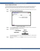
Step 1) 

Insert the CD supplied with the PR-8XX into an appropriate CD drive. 


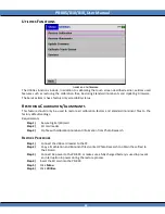
Step 5) 

Navigate to the drive containing the PR-8xx Installer CD, and double click on 

Setup


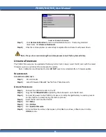
Note:     Do not insert the Bluetooth adapter into a USB port until prompted by the Driver Setup Wizard.


100 meter range is in open space using the Linksys USBBT100 Bluetooth adapter. 

Summary of Contents for Photo Research PR-810

Page 1: ...L User Manual PHOTO RESEARCH INC The Light Measurement People 7279 William Barry Blvd North Syracuse NY 13212 3349 Phone 315 701 0678 FAX 315 701 0679 Email sales pr photoresearch com URL www photores...

Page 2: ......

Page 3: ...nt contains proprietary information that is protected by copyright All rights are reserved worldwide No part of this document may be reproduced photographically electronically or by any other means wi...

Page 4: ...ept legal holidays to aid in technical support Call 315 701 0678 FAX 315 701 0679 or e mail for technical support support pr photoresearch com for instrument repair or calibration service pr photorese...

Page 5: ...USB 1 1 CONNECTOR 4 11 RS 232 CONNECTOR OPTIONAL 5 12 ANALOG OUTPUT CONNECTOR 6 OPTIONAL 12 BATTERY 14 REMOVING THE BATTERY 16 CHARGING THE BATTERY 16 STANDARD OBJECTIVE LENS 17 INSTALLING AND REMOVIN...

Page 6: ...G THE GAIN 31 SETTING ADAPTIVE ND AND GAIN 31 MAX EXPOSURE TIME PR 810L 33 SETTING THE FREQUENCY RESPONSE 34 ENABLING ANALOG OUTPUT 34 SETTING THE MEASURE SHUTTER STATE 34 FILE SETTINGS 35 ACCESSING T...

Page 7: ...ER ON WINDOWS XP 68 SETTING USB HUB TYPE 70 BLUETOOTH OPTIONAL 71 INSTALLING THE PHOTO RESEARCH SUPPLIED BLUETOOTH ADAPTER DRIVER ON HOST 71 ENABLE DISABLE BLUETOOTH 78 BLUETOOTH DISCOVERY MODE 78 PAI...

Page 8: ...05 CLEANING LENSES OPTICAL ACCESSORIES 105 CLEANING EXTERIOR SURFACES 105 RECALIBRATION 105 FACTORY REPAIR 105 IN WARRANTY REPAIR 105 SPECIFICATIONS 107 PR 810L 107 PR 810 107 PR 805 108 PR 8XX LENS C...

Page 9: ...rom a push button or peripheral device a Secure Digital SD card for measurement storage and a long lasting rechargeable Lithium ion Li Ion battery for more than 12 hours of operation PR 805 STANDARD E...

Page 10: ...easuring Apertures 3o 1 o 1 4o 1 8o o USB 1 1 Port o Secure Digital SD Card o BP 810 Rechargeable Lithium Ion battery pack o AC 810 6 6 Universal input AC Adapter o CD with drivers and Instruction Man...

Page 11: ...ge 3 View Finder View target measuring aperture 10 Analog Output Monitor PMT Signal 4 Measure Switch Execute measurement 11 I O Connector Panel Instrument connection panel 5 Power Switch Turn On I Off...

Page 12: ...The GUI allows the user to navigate through the PR 8xx s menu system 1 ACTIVE 2 AREA 3 FIGURE 2 PR 8XXSYSTEM MENU The Graphical User Interface consists of three major panes Item Description 1 Title b...

Page 13: ...gation Steps Preferences Date Time Root From System Menu navigate to and select Preferences Branch From Preferences navigate to and select Date Time End Node Leaf To traverse back to the System Menu s...

Page 14: ...ument Below are all system status icons and their corresponding indication Battery Charge ICON DESCRIPTION Green w 2 bars 100 Charge Green w 1 bars 66 Charge Yellow w bar 33 Charge Orange w bar blinki...

Page 15: ...following functions can be executed FIGURE 4 PR 8XXMEASUREMENT COMMAND BAR 1 Navigate Back to the previous menu screen 2 Abort a measurement 3 Save measurements to the SD card 4 Navigate through meas...

Page 16: ...libration due date and firmware version This screen can be viewed at any time by navigating to Menu System Information FIGURE 6 PR 8XXSTARTUP SCREEN I O PORTS The I O port panel is located on the left...

Page 17: ...nector optional EXTERNAL TRIGGER CONNECTOR 2 TABLE 4 I O PORT DESCRIPTION The PR 8XXis equipped with a 6 pin mini din connector that can be utilized for externally triggering a measurement and subsequ...

Page 18: ...2 GND Ground 3 IN Trigger Input Contact Closure 4 SPARE N C 5 OUT Trigger Output high side 6 OUT Trigger Output low side TABLE 5 PR 8XX EXTERNAL TRIGGER PIN OUT The following examples show sample driv...

Page 19: ...body Step 2 Insert the DC connector located on the opposite end of the adapter into the AC Adapter receptacle Step 3 The P Power and C Charging status indicators should now be illuminated Note The PR...

Page 20: ...e RS 232 Option 1 RJ 12 Jack on PR 8xx 2 RJ 12 to DB 9 adapter 3 6ft RJ 12 cable Please contact factory for custom RJ 12 cable lengths ANALOG OUTPUT CONNECTOR 6 OPTIONAL If the PR 8XX was purchased wi...

Page 21: ...nalog Output to Enabled and Measure Shutter to Always Open The Frequency Response can be set to the user s preference depending on the noise characteristics of the signal In OPEN the bandwidth is 20 K...

Page 22: ...lens The battery can be charged in the instrument using the AC Adapter or USB power or via the optional rapid charger accessory Warning Before using the battery for the first time charge the battery...

Page 23: ...2 3 4 Open battery door FIGURE 15 PR 8XX BATTERY COMPARTMENT CLOSE UP Description 1 Lithium Ion Li Ion Battery Pack 2 Battery Eject Button 3 Battery Compartment Door 4 Battery Door Latch TABLE 7 PR 8X...

Page 24: ...button located in the upper right hand corner of the battery compartment The battery will eject Remove the battery from the compartment 3 Close the battery door Make sure the Battery Door Latch has e...

Page 25: ...n steadily lit d Remove the battery when fully charged STANDARD OBJECTIVE LENS The standard objective lens for the PR 8XX is the MS 75 a 75mm f 2 8 MacroSpectar that focuses from 1 4 magnification to...

Page 26: ...Install Lens Uninstall Lens REMOVING THE OBJECTIVE LENS 1 Grasping the rear rubber ring see Figure 18 turn the lens counter clock wise until the lens separates from the lens mount INSTALLING THE OBJEC...

Page 27: ...is required in near real time FIGURE 19 V CURVE The primary unit of visible light power luminous flux used in photometry is the lumen One watt of radiant energy at the peak sensitivity of the eye 555...

Page 28: ...m2 Therefore to convert footlamberts to cd m2 multiply by 3 426 ILLUMINANCE Illuminance is the luminous flux incident on a surface per unit area and is given in lumens unit area This measurement is u...

Page 29: ...PR 805 810 810L User Manual 21 For Illuminance measurements in footcandles d is expressed in feet For lux d is expressed in meters...

Page 30: ...steps to help maximize the functionality and longevity of your new instrument Namely calibrating the touch screen display and charging the battery CALIBRATING THE CLICK SCREEN DISPLAY The Click screen...

Page 31: ...ck when finished SETTING INSTRUMENT PREFERENCES Several hardware parameters of the PR 8xx can be adjusted to the users liking They include Power Saving Brightness and Contrast Connectivity and optiona...

Page 32: ...played in the window adjacent to Power Saving In the preceding example Power Saving is enabled Click this field to Disable Power Saving It will then read Disabled 3 To instruct the instrument to shut...

Page 33: ...display Click the or icons on either side of the Brightness field The brightness level is adjustable from 0 to 100 3 To adjust the screen contrast Click the or icons next to the Contrast field The co...

Page 34: ...able these features FIGURE 27 SOUNDS AND ALERTS SCREEN Step 1 From the Preferences menu Click Sounds Alerts Step 2 The field to the right of the field descriptor displays the status of that feature To...

Page 35: ...TE AND TIME SCREEN Step 1 Click Date and Time from the Preferences menu Step 2 Click the or icons above or below the field of interest to scroll to the desired value The range for the Year field is 20...

Page 36: ...surements to average for the upcoming measurement to insure that proper calibration factors are applied From the main screen Click Menu or use the navigation keys The System Menu appears FIGURE 29 MAI...

Page 37: ...e equipped with 4 standard apertures 3 1 1 4 and 1 8 acceptance angles The angular values are valid when the instrument is being used with the MS 75 lens focused at infinity To modify the aperture sel...

Page 38: ...all ND filters the RS 3 SRS 3 SL 0 5X and SL 1X lenses Step 1 To select an Add on Accessory Click the or icon next to the Add on Accessory field to scroll through calibrated selections until the acce...

Page 39: ...e Choices are 1X 10X 100X and Maximum SETTING ADAPTIVE ND AND GAIN The PR 8xx utilizes the Photo Research Inc Adaptive Sensitivity algorithm During a measurement the optical radiation light is sampled...

Page 40: ...bling Adaptive Gain Selection Step 1 Navigate to Menu Setup Instrument Setup Step 2 In the Instrument Setup see Figure 32 screen set Gain selection to Note When adaptive gain is selected for the PR 81...

Page 41: ...set to Maximum When a measurement is made with the PR 810L the Max Time value becomes the maximum exposure time that the instrument will measure for If at the end of this time an insufficient signal i...

Page 42: ...t Connector on the side of the instrument Warning The impedance at the Analog Output connector is 50 ohms The device connected to the Analog Output connector must have an impedance of at least 1 MOhm...

Page 43: ...Main Manu after all options have been selected FIGURE 35 SECURE DIGITAL CARD FILE SETTINGS AUTO SAVE With Auto Save set to ON measurements are automatically saved to the file name in the SD Field in a...

Page 44: ...FILE Multiple measurements files with up to 200 measurements per file can be saved on the PR 8XX SD card The file name can be up to 8 characters long with no spaces or extensions To create a new file...

Page 45: ...easurement file Step 1 Insert the SD card with the measurement file to be deleted Step 2 Select the desired file to be deleted in the SD File field using the or icons Step 3 Click Note All measurement...

Page 46: ...have 5 minutes 300 sec to select one of the following options Step 1 Save measurements on SD card Click Yes Step 2 Shut down without saving Click No Step 3 Go back to previous menu and not shut down...

Page 47: ...iew option selects the memory location Internal RAM or External SD Click the or icon to toggle between Internal RAM and External SD Card SD FILE If External SD Card has been selected as the Current Vi...

Page 48: ...The relationship between cd m and footlamberts is 1 footlambert 3 426 cd m Luminance is measured whenever it is desirable to know the photometric brightness of self emitting devices transmissive objec...

Page 49: ...E LUMINANCE CONCEPT HOW TO MAKE A LUMINANCE MEASUREMENT If using an objective lens the first step is to align and focus the optical system lens and eyepiece on the target Lens focusing ring Grasp here...

Page 50: ...in focus If using a fixed focus lens move either the instrument or the target until sharp focus is achieved Do not use the eyepiece diopter adjustment to focus on the target Objective Lens Diopter adj...

Page 51: ...contact Photo Research for details It can also be used to approximate the luminance of more distant sources averaged over a circular field The acceptance angle of the probe is approximately 30 at the...

Page 52: ...approximate the luminance of more distant sources averaged over a circular field The acceptance angle of the adaptor is approximately 12 5 at the half power points and 14 at the 10 response points Th...

Page 53: ...E The optional accessories used to measure Illuminance are the CR 8xx and the RS 3 or SRS 3 The CR 8xx is a diffuser that serves as the surface upon which the incident light falls During calibration t...

Page 54: ...largest aperture can be used for this accessory The instrument will automatically set the Aperture selection to the largest system configured aperture Step 2 Remove the current Primary Accessory from...

Page 55: ...cessory to scroll to ICC 8xx depending on the instrument being used Make any other setup changes exposure sensitivity etc at this time Step 2 Remove the current Primary Accessory from the instrument t...

Page 56: ...S 3 and SRS 3 at the end of this section MEASURING PROCEDURE The procedure for making Illuminance and reflectance measurements with the RS 3 plaque are as follows Remove the protective cover from the...

Page 57: ...beads and runs off the material immediately Rinse with distilled water Note If the emery cloth grit is too fine the finish will be inadequate as the surface may become too smooth and reflect a high le...

Page 58: ...into the LED port at the open end of the accessory Two different sized LED ports are supplied with the LR 55 One is designed to accept 0 118 2 99 mm diameter LED s and the other accepts 0 205 5 21 mm...

Page 59: ...fies the report s requirement of average luminous intensity by providing both Condition A 2 and Condition B 6 5 measurement capabilities This is achieved by actuating a slide from the A position to th...

Page 60: ...ity millicandelas Step 5 Record the reading Step 6 Repeat Step 2 and select LR 127B Step 7 Click the MEASURE button to make a measurement Record the results Step 8 Find the average of the readings fro...

Page 61: ...PR 805 810 810L User Manual 53 OVERVIEW Figure 56 IS 8xx Outer View...

Page 62: ...rument MOUNTING THE LED Step 1 Loosen the Set Screw see Figure 57 by turning it counter clockwise Step 2 Remove the Mounting Tube from the Collar by gently pulling away from the sphere If there is any...

Page 63: ...Collar until the Mounting Tube just touches the top of the Height Adjustment Screw Step 6 Tighten the Set Screw to hold the Mounting Tube in place DO NOT OVER TIGHTEN FIGURE 58 HEIGHT ADJUSTMENT MAKI...

Page 64: ...ontinuous Measurements feature should not be confused with the Measurements to Average function FIGURE 59 TIMED MEASUREMENTS SCREEN SETTING TIMED MEASUREMENTS PARAMETERS TIMED MEASUREMENTS Step 1 Navi...

Page 65: ...ement Button to initiate the Timed Measurement Sequence CONTINUOUS MEASUREMENTS Step 1 Navigate to the Timed Measurements screen by touching Menu then Setup then Timed Measurements Step 2 Click the Ti...

Page 66: ...ied The Photometer factor can be modified using one of two methods The user can enter a calibration value or enter the absolute and have the PR 8xx correct itself following a measurement Warning When...

Page 67: ...PR 805 810 810L User Manual 59 FIGURE 62 CORRECTION FACTOR ENTRY Step 3 Enter the new factor as calculated by Step 4 Click Back when done...

Page 68: ...ed Make sure the source and instrument are sufficiently warmed up Step 2 Click on Menu Setup PMT Calibration FIGURE 63 PMT CALIBRATION SCREEN Step 3 From the PMT Calibration Screen see Figure 63 Click...

Page 69: ...the PR 8XX on the source sample to be measured Make sure the source and instrument are sufficiently warmed up Step 2 Click on Menu Setup Correction Factors FIGURE 64 PMT CALIBRATION SCREEN Step 3 Fro...

Page 70: ...l calibration factors and standard illuminant files to the factory default settings Requirements Step 1 Secure Digital SD card Step 2 SD card reader Step 3 Zip file with calibration illuminant informa...

Page 71: ...nt to update Note Calibration and Illuminant factors DO NOT have to be reloaded after a firmware update REQUIREMENTS SECURE DIGITAL SD CARD Step 1 SD card reader Step 2 Latest firmware PR8xxHW hex fil...

Page 72: ...67 PR 8XX FIRMWARE UPDATE PROMPT Step 9 If Yes was selected the firmware is automatically updated Step 10 At the screen that appears following the completion of the update press OK to restart the inst...

Page 73: ...port can only be used to recharge the battery The PR 8XX cannot be powered solely off the USB hub INSTALLING THE USB DRIVER WINDOWS XP ONLY Prior to using Remote Control commands or Photowin software...

Page 74: ...click Next FIGURE 69 PR 8XX USB DRIVER INSTALL Step 6 Insert the CD supplied with PR 8XX into an appropriate CD drive Step 7 Choose Search for the best driver in these locations then browse to CD Driv...

Page 75: ...PR 805 810 810L User Manual 67 Step 9 Click on Continue Anyway FIGURE 71 WINDOWS XP COMPATIBILITY WARNING FOR PR 8XX USB DRIVER Step 10 Click Finish FIGURE 72 PR 8XX USB DRIVER INSTALL COMPLETE...

Page 76: ...ficient current available for the USB device PR 8XX Windows will issue a warning and disable the device DETERMINING USB HUB POWER ON WINDOWS XP Step 1 Click on Step 2 Right click on My Computer in the...

Page 77: ...PR 805 810 810L User Manual 69 Total power available Total power required FIGURE 74 USB POWER SCREEN...

Page 78: ...acent to USB Hub Type until Low Power appears When the PR 8XX is powered on the instrument will run partially on the battery and partially on the USB power This will help preserve the battery charge a...

Page 79: ...TOOTH ADAPTER DRIVER ON HOST The USB Bluetooth adapter enables Bluetooth connectivity on the PC host side The adapter allows the Host to communicate with the PR 8XX wirelessly Before Bluetooth communi...

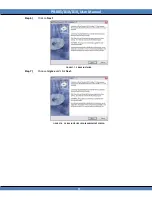
Page 80: ...PR 805 810 810L User Manual 72 Step 6 Click on Next FIGURE 77 PR 8XX INSTALLER Step 7 Choose I Agree and click Next FIGURE 78 PR 8XX INSTALLER LICENSE AGREEMENT SCREEN...

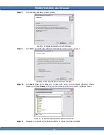
Page 81: ...screen appears FIGURE 80 PR 8XX INSTALLER INSTALL DIRECTORY SELECTION Step 10 Click Next then go to Step 11 to install the driver to the default directory Photo Research or click Browse to bring up th...

Page 82: ...SpectraWin2 can also be installed if desired FIGURE 82 PR 8XX UTILITIES COMPONENT SELECTION Step 13 Click Next to start the installation FIGURE 83 PR 8XX INSTALLER START INSTALLATION Step 14 The WIDCO...

Page 83: ...he driver will prompt for the USB dongle DO NOT INSERT DONGLE UNTIL PROMPTED TO DO SO Step 19 Click Finish FIGURE 86 WIDCOMM DRIVER INSTALLATION COMPLETED Step 20 The My Bluetooth Places icon appears...

Page 84: ...Next FIGURE 88 INITIAL BLUETOOTH CONFIGURATION WIZARD Step 23 Click Next allowing the default settings FIGURE 89 DEVICE NAME AND TYPE SELECTION Step 24 Make sure that only Bluetooth Serial Port is ch...

Page 85: ...25 Click Skip FIGURE 91 BLUETOOTH FIND DEVICE PROMPT Step 26 Click Finish to complete the Initial Bluetooth Configuration Wizard setup FIGURE 92 INITIAL CONFIGURATION WIZARD COMPLETE Step 27 The Blue...

Page 86: ...No Icon Bluetooth Off Enabled Bluetooth enabled and connectable by previously paired remote host Enabled Discoverable Blinking Bluetooth enabled and discoverable by any remote host Bluetooth Link Est...

Page 87: ...e paired with a remote host only once once pairing has occurred both the remote host and the PR 8XX will remember there pairing information This allows the remote host to automatically when Bluetooth...

Page 88: ...PR 805 810 810L User Manual 80 FIGURE 96 BLUETOOTH CONNECTIVITY SETUP WINDOW...

Page 89: ...he icon located on the desktop Step 2 Click on Add a Bluetooth Device located in the top right corner of the window FIGURE 97 MY BLUETOOTH PLACES Step 3 The Bluetooth Setup Wizard will appear Step 4 C...

Page 90: ...e PR 8XX below the icon Select the instrument and then click on Next FIGURE 98 REMOTE HOST DEVICE SEARCH WIZARD Make sure that is selected via the drop down menu Step 8 Give a name for the PR 8XX inst...

Page 91: ...H PIN CODE REQUEST Step 14 If successfully paired a serial connector icon will appear in My Bluetooth Places The PR 8XX will also indicate a successful pairing and connection by displaying the icon an...

Page 92: ...exadecimal RS 232 OPTIONAL The traditional RS 232 I F allows for interfacing to ATE environments and older generation PC systems The below diagrams depicts the connection between the PR 8xx and the ho...

Page 93: ...uching on Menu then Preferences 2 ClickRS 232 Connectivity 3 The following screen will appear Figure 103 RS 232 Connectivity Baud Rate Setup 4 Click the next to the RS 232 Baud Rate text field to sele...

Page 94: ...8XX Communication protocol is identical to RS 232 communications The USB driver emulates an RS 232 interface including opening a COM port setting a baud rate parity stop bits and flow control This mak...

Page 95: ...f time See How to Adjust Power Savings Settings of this manual for more information Step 3 Connect the 8xx to the PC via the USB interface cable FIGURE 104 PR 8XX USB CONNECTOR Step 4 Click on on your...

Page 96: ...window that appears FIGURE 106 COM PORT SELECTION IN HYPER TERMINAL If in doubt about which COM port is correct the proper port can be identified in the Device Manager system screen To access this sc...

Page 97: ...PR 805 810 810L User Manual 89 FIGURE 108 SYSTEM PROPERTIES MENU Step 17 Click on Device Manager Step 18 Note the COM port assigned to the PR 8XX FIGURE 109 WINDOWS XP DEVICE MANAGER...

Page 98: ...RE 110 WINDOWS XP COM PROPERTIES WINDOW Step 20 The main HyperTerminal appears Type PHOTO case sensitive Step 21 REMOTE MODE is displayed in the HyperTerminal window The PR 8xx is now ready to accept...

Page 99: ...cy of light source I Requests instrument status or error report from PR 8XX L Defines measurement title Maximum of 20 characters M Measure command for the PR 8XX Returned datum depends on the accompan...

Page 100: ...ff ff Hertz Period nnnnn milliseconds If all OK else NNNN CR LF NNNN Error code I Purpose Return instrument status error report Syntax I CR Response 0000 CR LF If all OK else NNNN CR LF NNNN Error cod...

Page 101: ...l be that stored in the internal memory RAM of the instrument instead of the SD card data in response code refers to the specific measurement data set returned based on the data code sent to the instr...

Page 102: ...LF NNNN Error code Note Accessory Codes can be found by running report 116 command D116 See the Data Codes section for specific details SB Select Add on Accessory 2 An Add on accessory is one that is...

Page 103: ...perture code Response 0000 CR LF If all OK else NNNN CR LF NNNN Error code Note See Data Code 117 for details on aperture codes SG Gain Electronic gain modes choices are x1 x10 x100 Maximum PR 810L On...

Page 104: ...else NNNN CR LF NNNN Error code SO CIE Observer Photometric and Colorimetric values can be calculated using either CIE 2 or 10 Standard Observer data sets Use this specifier to choose the CIE data set...

Page 105: ...er Frequency In Auto Sync mode the instrument measures the frequency of the source to determine its period The exposure time is then automatically altered so that it is an even multiple of the source...

Page 106: ...Measure Shutter Control Controls the actions of the measure shutter When set to 0 the measure shutter will be closed after each measurement and a dark measurement will be taken When Measure shutter c...

Page 107: ...the following table STAT is the returned error code If STAT is all zeros 00000 no error has occurred during the request All other values for STAT relate to an error condition Refer to the Remote Mode...

Page 108: ...s Sync mode description sync period in milliseconds 110 status Instrument Serial Number 111 status Model Number 112 status Number of Accessories Number of Apertures 114 status Firmware Version 116 sta...

Page 109: ...CRLF where Y Photometric brightness e g Luminance or Illuminance etc Output Example 00000 0 1 449e 01 13 Output Format STAT Gain Exposure Time CRLF Output Example 00000 x1 80 msec 14 Output Format ST...

Page 110: ...000 1 04 01 2008 19 14 04 2 04 01 2008 19 14 07 601 Output Format STAT PrimaryAcc AddOn1 AddOn2 AddOn3 Aperture ID Units Gain ND Max Exp Time of Cycles to Average Freq Response Filter MeasureShutter S...

Page 111: ...setup command 1002 Invalid primary accessory code 1003 Invalid Addon 1 accessory code 1004 Invalid Addon 2 accessory code 1005 Accessory is not a primary accessory 1006 Accessory is not an Addon acces...

Page 112: ...Invalid R command 1025 Invalid Addon 3 accessory code 1026 Invalid sensitivity mode 0 Standard Mode 1 Extended Mode 1035 Parameter not applicable to this instrument 2000 This error code is returned wh...

Page 113: ...factory However changes in calibration are inevitable due to the effects of aging temperature and dirt accumulation Therefore for best results periodic recalibration is recommended To maintain the in...

Page 114: ...www photoresearch com to assign a Returned Material Authorization RMA number to your instrument before returning it to Photo Research for service The instrument should be brought or shipped prepaid to...

Page 115: ...ms to 10 secs Battery Rechargeable Lithium ion 12 hours continuous operation Weight 3 75 lbs 1 7 kg Operating 34 to 95 F Temperature 1 to 35 C PR 810 Parameter Specification Detector Photomultiplier T...

Page 116: ...tion 16 bits Standard Apertures 1 Optional Apertures 3 2 1 2 Luminance Range 0 0009 to 8 100 fL Luminance accuracy Against NIST lumi nance standard 2 Luminance repeatability 1 Display 3 5 Color Touch...

Page 117: ...to 0 132 mm 0 89 0 294 mm to 1 32 x 0 436 mm MS 2 5X 46 mm 1 53 mm 1 02 mm 0 51 mm 0 225 mm 0 128 mm 0 102 mm 0 064 mm 0 051 mm 0 51 x 0 168 mm MS 5X 28 mm 0 78 0 52 mm 0 26 mm 0 13 mm 0 065 mm 0 052...

Page 118: ...4050 1 80E 5 to 16200 7 20E 5 to 64800 2 88E 4 to 259000 4 50E 4 to 405000 1 15E 3 to 1037000 1 80E 3 to 1960000 4 28E 5 to 38556 PR 810 Aperture Access 3 2 1 1 2 1 4 0 2 1 8 0 1 1 x 0 33 MS 75 1 00E...

Page 119: ...o 5060 2 25E 3 to 20300 9 00E 3 to 81000 MS 5X 4 00E 4 to 3 6 9 00E 4 to 8 10 3 60E 3 to 32400 1 44E 2 to 130000 MS 7 5 1 00E 4 to 900 2 25E 4 to 2030 9 00E 4 to 8100 3 60E 3 to 32400 LA 800 1 00E 4 t...

Page 120: ...PR 805 810 810L User Manual PR 8XX OUTLINE DRAWINGS 112...

Reviews: