Basic Control Set-Up
The control set-up on your spa is designed to give you fingertip control of the heater, air induction, and whirlpool/filter pump
and blower systems of your unit from inside or outside your spa. Follow the basic control set-up described on page 9 to
familiarize yourself with the several functions of the control panels.
CAUTION
Do not turn on power to the spa unless it is filled with water to the normal water level, which is approximately 6"
below the spa rim (See water level mark on skimmer). If the spa’s motor/pump is actuated when there is not sufficient
water in the unit, the circulation pump and heater could be irreparably damaged. Not heeding this caution will nullify
the warranty. In addition to damaging the unit, operating the spa with insufficient water could cause a fire.
Using a garden hose, fill the spa with water to the water
line at water level mark on skimmer.
At the house service panel, turn on the circuit breaker or
a switch that controls the electrical service to your spa.
Plug the line cord into a 115VAC 20 AMP receptacle.
(Make sure there is no other appliance on that circuit.)
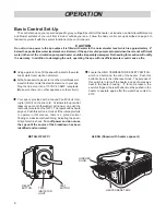
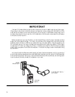
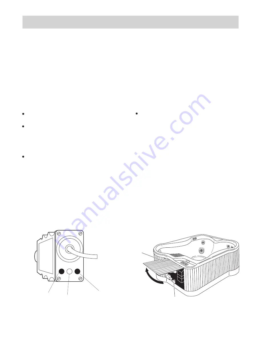
Locate the HIGH TEMPERATURE SAFETY SWITCH,
which is a button on the end of the heater. Push this
button to be sure it is in the reset mode. The purpose of
this switch is to turn off the heater in case of excessive
heat in the heater housing. If, for some reason, the
switch is tripped, the reset button must be pushed in the
heater to operate again after the water has cooled to
90
°
F.
Your spa is provided with a Ground Fault Circuit Inter-
rupter (GFCI) on the line cord. At initial start-up (and at
least once a month thereafter), with power on, push the
test button located on the GFCI. The reset button should
pop out. Push this button in to reset. If the interrupter fails
to operate in this manner, there is a ground current
flowing or a device malfunctioning, indicating the possi-
bility of electric shock. Turn off power and do not use
the spa until the source of the breakdown has been
identified and corrected.
6
ALEXA (Shown with heater exposed.)
OPERATION
HEATER RESET BOX
HINDGED
DOOR
TEST
RESET
RESET
BUTTON
TEST
BUTTON
TRIP
INDICATOR
LIGHT
DETAIL OF GFCI


