54
insTAllATiOn direcTiVe
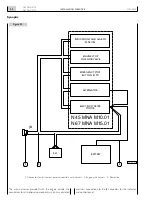
N45 MNA M10
N67 MNA M15
MAY 2006
!#
*#
#!
#'
6
10
¬
*"
*#
*"
''
-
7
$
"
n"
2,
--
*
8
#
#
4!
-/
¬!
&3
3!
¬
*#
*"
3)&
!
33
3"0/
3!
4!
3",!
3#0
336
!1
A
"!44¬--
"!44¬''
n"!44¬--
''
%#
7
6
)
4
+
*36
*&
''
2,
$¬
$¬
-!
-0
3
,
!.
+
6
'
.
6"
( -
".
3
6"
6
.
!.
!
2
'2
":
+
6.
,
'
( -
".
3
3.
6
.
!.
!
2
:
"
+
6.
,
'
*
+3"
)
)
component
terminal
connection
Jc: connector
16: terminal
Fuse code
component
code
component code
or connector code
cable colour
Quadro princ N 100-150 AFAM
Minimum cable cross
section in mm
2
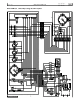
Wiring diagram key
General conditions for the preparation and interpretation of wiring diagrams:
o
Key switch open
o
engine not running
o
Liquids at efficient levels and pressures
Figure 4
20. M10.01/M15.01 WIRING DIAGRAMS


