


47
insTAllATiOn direcTiVe
N45 MNA M10
N67 MNA M15
MAY 2006
*"
2,
*#
*#
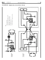
Figure 42
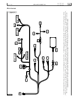
CONNECTORS OF THE JB - JC EXTENSION WIRE
HARNESS, SEEN FROM THE COUPLING SIDE
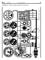
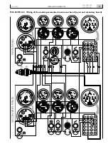
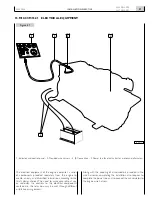
Figure 4
1. JB-JC extension wire harness - 2. Wiring to be carried out by the installing technician.
05_010_N
1
2
5
6
10
13
14
9
4
3
8
7
11
12
15
16
16
15
12
11
8
3
4
9
14
13
10
6
5
2
1
7
*"
*#
05_013_N
1
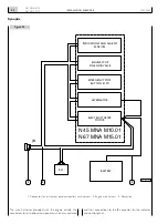
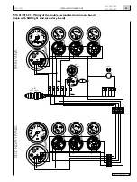
BATTery
enGine
eQUiPMenT
MAin
insTrUMenT
PAnel
secOndAry
insTrUMenT
PAnel
Pin
cOnnecTOr
cABle cOlOUr
1
red
2
sky blue
3
sky blue - black
4
black
5
green
6
yellow
7
blue
8
green - black
9
orange
10
white
11
purple
12
pink - black
13
pink
14
white - black
15
grey
16
brown
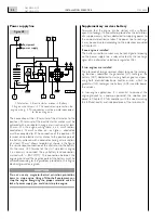
To identify the functions served by the individual lines, refer
to the electrical diagrams in Chapter 20.
Connectors of the JB - JC extension
wire harness
2
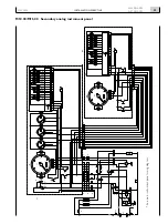
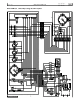
Synoptic of the connections of the analog panels


