


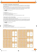


Wärmeabgabe unter Bedingungen maximaler Belastung
Zur Unterstützung des Installationspersonals und zur Vermeidung komplizierter Berechnungen liefern wir in den nachstehenden Tabel-
len einige Beispiele, die auf einfache Weise zur Bestimmung der unter Bedingungen maximaler Belastung erforderlichen Wärmeabgabe
verwendet werden können.
Dabei werden zwei Situationen geschildert, bei denen der Druckabfall am Mischventil und am Bypassventil auf der Sekundärleitung
100 mbar und 150 mbar betragen. Durch Hinzufügung dieser Werte zu Druckverlusten des ungünstigeren Kreises kann die Mindest-
förderhöhe der Umlaufpumpe berechnet werden. Zur Wahl der am besten geeigneten Pumpe muss die an die Verbraucher zu liefernde
Fördermenge berücksichtigt werden, die auf einfache Weise mit folgender Formel berechnet werden kann:
R
M
p
T
T
E
Q
860
mit Ep in kW und Q in l/h.
mit:
Tc = Kesseltemperatur (°C)
Tr = Rücklauftemperatur von Verbrauchern (°C)
Tm = Temperatur des den Verbrauchern zugeführten Mischwassers (°C)
Ep = Wärmeabgabe bei maximaler Belastung (kW)
Bypass = Anzahl der Umdrehungen zum Öffnen des Bypass auf der Sekundärleitung (Mikrometerschraube)
Thermal output in maximum load conditions
To help installation personnel and avoid complicated calculations, we provide in the tables below some examples which can be easily
used to identify the thermal output required in maximum load conditions.
Two different situations are outlined where the drop in pressure on the mixer valve and the secondary balance bypass are respectively
100 mbar and 150 mbar. By adding this value to the losses of load in the worst-case loop, it is possible to calculate the minimum head
of the circulation pump. In order to select the most appropriate pump, add the capacity head and the total capacity to utilities. The
capacity value is easily calculated using the following formula:
R
M
p
T
T
E
Q
860
with Ep in kW and Q in l/h.
Key:
Tc = boiler temperature (°C)
Tr = return temperature from utilities (°C)
Tm = temperature of the mixed water sent to utilities (°C)
Ep = thermal output in maximum load conditions (kW)
Bypass = opening turns number of secondary bypass. Turns number refers to the micrometric adjustment dowel
∆p = 100 mbar
T
C
(°C)
T
R
(°C)
T
M
(°C)
E
p
(kW)
Bypass
T
C
(°C)
T
R
(°C)
T
M
(°C)
E
p
(kW)
Bypass
40
30
35
13
4
40
30
38
13
1
45
30
35
16
Aperto
Open
45
30
38
20
3 ¼
50
30
35
50
30
38
27
Aperto
Open
55
30
35
55
30
38
60
30
35
60
30
38
65
30
35
65
30
38
70
30
35
70
30
38
75
30
35
75
30
38
40
30
36
13
2 ¼
40
30
39
13
½
45
30
36
20
Aperto
Open
45
30
39
20
2 ¼
50
30
36
50
30
39
27
6 ¼
55
30
36
55
30
39
30
Aperto
Open
60
30
36
60
30
39
65
30
36
65
30
39
70
30
36
70
30
39
75
30
36
75
30
39
40
30
37
13
1 ½
40
30
40
13
Chiuso/Closed
45
30
37
20
5 ½
45
30
40
20
1 ¾
50
30
37
23
Aperto
Open
50
30
40
27
4
55
30
37
55
30
40
33
Aperto
Open
60
30
37
60
30
40
65
30
37
65
30
40
70
30
37
70
30
40
75
30
37
75
30
40
IVAR_UNIMIX_E_DE.indd 13
05-11-2008 10:04:47