


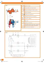


Anschluss der Pumpe
Die Umlaufpumpe (10) des Sekundärkreises muss zwischen zwei drehbaren Ansät-
zen montiert werden, wobei darauf zu achten ist, dass die Pumpe nach oben pumpt
(Abb. F). Es wird auch empfohlen, passende Flachdichtungen einzusetzen, wie sie nor-
malerweise mit der Umlaufpumpe geliefert werden.
Der Elektroanschluss der Pumpe darf nur von qualifiziertem Fachpersonal vorgenom-
men werden.
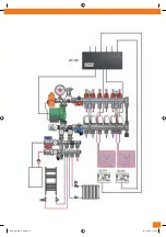
WICHTIG:
Wird eine herkömmliche Pumpe mit fester oder in drei Stufen verstellbarer
Drehzahl verwendet, so wird dringend empfohlen, auf der Sekundärleitung eine etwai-
gen Überdruck ausgleichende Bypassleitung einzubauen. Zum Beispiel kann der Artikel
AC 666 leicht an einer Anschlussstelle des Verteilers angebaut werden.
Die Einbaurichtung des Bypassventils ist besonders zu beachten. Der Bausatz muss so
positioniert werden, dass sich der schwarze Knopf am unten befindlichen Rücklaufver-
teiler befindet, wie dies in Abbildung G gezeigt ist. Bei Verwendung einer elektronisch
gesteuerten Verstellpumpe ist die Montage der Überdruck-Bypassleitung jedoch nicht
erforderlich.
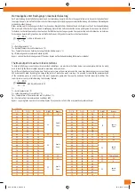
Bei einer 130 mm langen Pumpe müssen die Verteiler auf 200 mm breiten Halterun-
gen und bei Pumpenlängen von 180 mm auf Halterungen einer Breite von 250 mm
befestigt werden.
Connection of the pump:
the secondary circulation pump (10) must be fitted between two rotary nuts, making
sure that the direction of pump thrust is upwards (Fig. F). It is also advisable to fit
suitable flat gaskets that are generally supplied with the circulation pump.
The electrical connection of the pump must exclusively be made by qualified person-
nel.
IMPORTANT:
if a traditional fixed speed or three speed pump is used, it is strongly advi-
sed to fit a differential overpressure bypass to the secondary circuit. Article AC 666, for
example, can be easily installed as a terminal on the distribution manifolds. Take great
care as regards the assembly direction of the bypass valve: the kit must be positioned
so that the black knob is on the return manifold (the one at the bottom) as shown in
Figure G. If a variable speed pump with electronic control is used, the overpressure
bypass, on the other hand, does not have to be fitted.
With pump length 130 mm manifolds must be fitted on brackets with centres 200
mm, for pump length 180 mm manifolds must be mounted on brackets with centres
250 mm.
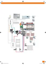
Füllen der Anlage
Zum richtigen Füllen der Anlage ist der Anschluss des Füllsystems am Füll-/Entlee-
rungshahn (8) erforderlich, wobei der Kugelhahn (7b) in offener Stellung verblei-
ben muss. Der Kugelhahn (7a) auf dem Zulauf ist zu schließen und das manuelle
Entlüftungsventil (9) zu öffnen. Die Kappe auf dem automatischen Entlüftungsventil
(5) lockern und dann die Anlage füllen. Sobald aus dem manuellen Entlüftungsventil (9)
Wassertropfen austreten, ist der Füllvorgang abgeschlossen. Diese Maßnahme muss
für jeden Kreislauf getrennt vorgenommen werden.
Filling the plant:
correct filling of the plant requires connecting the filling system to the fill/empty cock
(8), leaving the ball valve in an open position (7b); close the ball valve (7a) on delivery,
open the manual breather (9), slacken the cap on the automatic breather (5) and then
fill the plant. As soon as drops of water emerge from the manual breather (9), filling is
complete. This operation must be performed separately for every circuit.
F
G
IVAR_UNIMIX_E_DE.indd 10
05-11-2008 10:04:40