


Page 15
Operation and Maintenance Instructions
Envistar Top 04-21
DSET.181201.00.EN
Continuous product development may give rise to specification changes without notice.
4 Wiring instructions and fuse protection
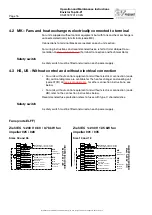
4.1 MX – Complete control equipment and UC – Complete electrical
connection to terminal (without DUC).
Applies to:
• units supplied prewired with complete, integrated Siemens Climatix control
equipment (code MX).
• units supplied without process unit (DUC) but with sensor and damper ac-
tuator connected electrically to the terminal (code UC). Fans and heat ex-
changers are fused and connected electrically to the terminal. The terminal
connections are positioned at a shared place in the unit. For further con-
nection to an external process unit, we recommend using a multi-conductor
cable.
Safety switch
A safety switch must be fitted and wired on each power supply.
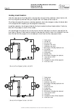
Wiring diagrams
For wiring diagrams for units with control equipment, see the order-unique wiring
diagram supplied with the unit at
(Control Diagram).
Unit functions, power supply and fuse protection
For recommended fuses, refer to Order Unique Documentation at
(Technical Data and Control Diagram), or the product
program IV Produkt Designer.
• Top 04-16 have a shared power supply for all unit functions as standard, but
can be ordered with separate power supplies on special order.
Top 21 have separate power supplies as standard.
• Electric heaters (air heater electric) have a power supply 3x400 V as
standard.
A special coil or a transformer is required for a 230 V power supply.
• Fuses with type C characteristics are recommended.


