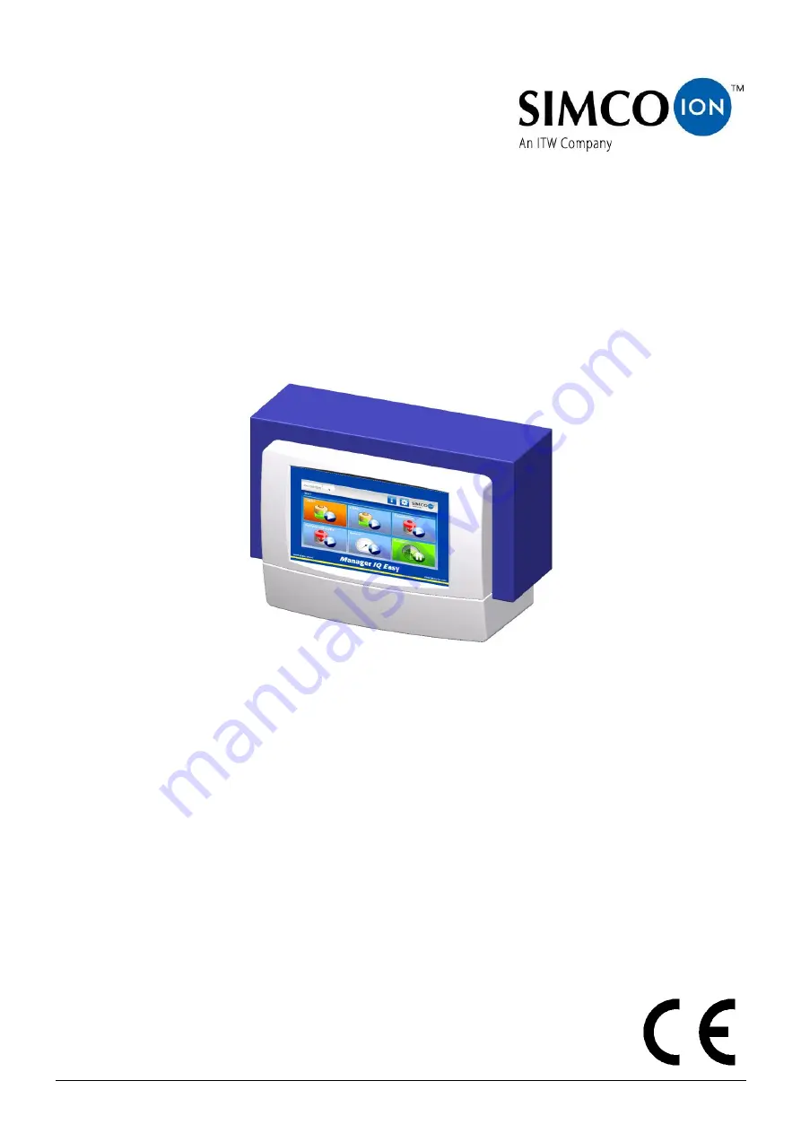
ITW SIMCO ION Manager IQ Easy Manual Download Page 1

ManagerIQEasy_UM_9752103002_GB_V3_1 


Manager IQ Easy 


Control unit 


SIMCO (Nederland) B.V. 
Postbus 71 
NL-7240 AB Lochem, The Netherlands 
Telephone  +31 (0)573-288333 
Fax  

+31 (0)573-257319 

Email 

[email protected] 

Internet 

http://www.simco-ion.nl 

Trade Register Apeldoorn No. 08046136 

Summary of Contents for SIMCO ION Manager IQ Easy

Page 1: ...1 Manager IQ Easy Control unit SIMCO Nederland B V Postbus 71 NL 7240 AB Lochem The Netherlands Telephone 31 0 573 288333 Fax 31 0 573 257319 Email general simco ion nl Internet http www simco ion nl Trade Register Apeldoorn No 08046136 ...

Page 2: ...5 4 6 Ethernet connection 15 5 4 7 Serial communication COM ports 16 5 4 8 Installing the protective cover 16 5 5 Mounting the Manager in a machine panel 16 6 Commissioningand operation 21 6 1 Terminology used 22 6 2 Switching on the Manager IQ Easy 23 6 3 The main screen 24 6 4 Devices 26 6 5 Operating modes 27 6 5 1 Standby and Run 27 6 5 2 Autorun mode 27 6 6 Remote on off 28 6 7 Status informa...

Page 3: ...r Sensor version V5_2 only 86 6 19 1 Activating and deactivating sensor segments via the settings screen Expert user 86 6 19 2 Activating and deactivating sensor segments via the Graphics screen Expert user 87 6 20 Enabling and disabling Sensor segments Expert user 88 6 20 1 Enabling and disabling Sensor segments via the settings screen Expert user 88 6 20 2 Enabling and disabling Sensor segments ...

Page 4: ...et and EtherNet IP only 120 6 31 2 1 Setting the Fieldbus network parameters using a DHCP server 121 6 31 2 2 Setting the Fieldbus network parameters without using a DHCP server 122 6 31 3 Settingthe parameters Domainname Hostname ProfiNetandEtherNet IPonly 124 6 31 4 Setting the network Device name ProfiNet only 126 6 31 5 Setting the Fieldbus Device ports mapping parameter s 129 6 31 6 Setting t...

Page 5: ...t Read through the entire manual before installing and commissioning the product Follow the instructions set out in this manual to ensure proper operation of the product and to retain your entitlement under the guarantee The guarantee terms are set out in the General Terms and Conditions of Sale of SIMCO Nederland B V Explanation of symbols The following symbols may appear in this manual or on the...

Page 6: ...be configured To further expand the system to up to 30 Devices the system has 2 serial COM connectors for connecting Extension IQ Easy control units The Manager IQ Easy is available with 24V DC input and as a universal 100 240V AC 50 60Hz version A special version of the Manager IQ Easy is also available that can be used with emergency off installations whereby the Manager IQ Easy remains supplied...

Page 7: ...will then be displayed If a tab has several pages you can scroll through them using the and the buttons Each tab contains specific information about the connected device which will vary for each type of device More or less information is displayed depending on the log in level for the user level Information Various parameters settings limit values operation modes and current readings are displayed...

Page 8: ...ManagerIQEasy_UM_9752103002_GB_V3_1 7 On each tab you can set the Device to standby or active mode Specific information of each tab is described in the manual of the corresponding Device ...

Page 9: ...other corrosive materials are used Danger Make sure that the equipment is properly earthed Earthing is necessary to ensure proper and safe operation and to prevent electric shocks upon contact The AC version is earthed through the power cable Plug this into an earthed outlet With the 24 V DC version the earthing connector of the 24 V power connector has to be connected to the machine earthing or a...

Page 10: ... and vibration Free of dust and vibration 100 240V AC version 24V DC 3A max per port total max 9A Device output 24V DC version 24V DC 3A max per port total max 13A Machine I O Digital inputs 10 30 V 25mA max Analog input 0 10V 0 6mA 0 20mA 4 20mA Digital outputs OE OC 24V DC nom max 30V 25mA USB 3x USB 2 0 Ethernet 1x RJ45 8 pin connector Fieldbus optional 1x Anybus interface Weight 5 5 kg 100 240...

Page 11: ...ManagerIQEasy_UM_9752103002_GB_V3_1 10 Figure 3 Drilling template Manager IQ Easy and Extension IQ Easy ...

Page 12: ...that you have received the correct version Check that the packing bill data matches the data of the product received Check whether the voltage shown on the rating plate corresponds to the mains voltage you intend to use If you have any problems or are unsure please contact Simco Ion or your regional agent 5 2 General Place the Manager on a well visible and easily accessible place on or nearby the ...

Page 13: ...ecure the lower mounting eye of the Manager with a suitable bolt 5 4 Electrical installation Warning Disconnect the power supply before carrying out any work on the unit The electrical installation must be carried out by an electrical engineer with the relevant training and qualifications Make sure that the equipment is properly earthed Earthing is necessary to ensure proper and safe operation and...

Page 14: ... routed through this cable If the desired length exceeds the maximum specified length a cable with a larger diameter for the used wires may be selected so that the required supply voltage is still available during operation For this Simco Ion provides separate M12 5 pin connectors for connecting these cables the connection between the Manager and the Device is 1 1 see also Figure 6 Figure 6 Wiring...

Page 15: ...PLC The digital outputs can be configured in the Manager both as Open Collector OC and Open Emitter OE For this see Section 6 12 and 6 14 By default these are configured as Open Emitter The output is then switched from the 24 V DC The PLC input can then be connected to the external GND For connecting these see figure 7 Figure 7 Wiring digital outputs on the machine interface connector Available si...

Page 16: ...ector 5 4 5 Fieldbus connection With an optional Fieldbus connection EtherNet IP ProfiNet etc controls such as remote on off warnings and alarms can be linked to a machine control PLC Setpoint settings and reading back of readings are also possible when using a Fieldbus For this a Fieldbus interface module is mounted into the Anybus slot at the factory For connecting these fieldbuses follow the ge...

Page 17: ...able protection cover can be mounted 5 5 Mounting the Manager in a machine panel Figure 9 Manager IQ Easy mounted in a machine panel The Manager IQ Easy can be mounted into a machine panel so that only the plastic part of the Manager is visible The wiring will then be hidden behind the machine panel The maximum thickness of the machine panel is 6 mm Follow the steps below to mount the Manager IQ E...

Page 18: ...l away the plastic front from the housing The plastic part can be loosened using a larger flat screwdriver There are two recesses below the plastic part for this Note Do not pull on the wiring between the front and the housing Remove all connectors from the front Remove the M5 tap bolts and washers 1 and the 4 snap connectors 2 and 3 from the housing ...

Page 19: ...e the housing behind the machine panel and secure it with the 4 tap bolts and washers 1 Make sure that the wires are not squeezed between the housing and the machine panel Screw the four snap connectors into the housing through the machine panel ...

Page 20: ...ManagerIQEasy_UM_9752103002_GB_V3_1 19 Mount the wiring connectors from the housing back onto the front Click the front onto the four snap connectors on the machine panel ...

Page 21: ...ManagerIQEasy_UM_9752103002_GB_V3_1 20 ...

Page 22: ...e the protection film from the touchscreen Switching on Make sure that supply voltage is available in the power cable Switch the Manager on using the power switch Note The Manager is suitable for continuous operation Switching off the manager means that all connected Devices no longer receive the supply voltage and hence are no longer operational ...

Page 23: ...rol panel with which the Manager IQ Easy can be given instructions to operate the system Statuses settings and readings are also displayed Backplane IQ Easy The component in the Manager IQ Easy allowing 6 Devices to be connected to the IQ Easy System Extension IQ Easy also called Extension Box Extra boxes to be added with which 6 extra Devices per box can be connected to the IQ Easy System A maxim...

Page 24: ...n be adjusted to adjust the operation of Devices For faster response the Manager IQ Easy is equipped with a Remote I O control These inputs and outputs can be connected to a PLC to be able to report the system status of the Manager IQ Easy to the PLC but the PLC can also control the Manager IQ Easy to switch Devices on and off faster via a Remote On Off signal For advanced Remote I O control the M...

Page 25: ...d The setting of parameters is described in Section 6 12 The tab TabM displays the Devices connected to the Manager IQ Easy The tabs Tab1 to Tab4 are only visible when the corresponding Extension IQ Easy is connected and active The Devices connected to the Extension IQ Easy are displayed in these tabs If a tab is selected it will have a light grey colour if a tab is not selected it will have a sli...

Page 26: ...n Extension IQ Easy or a Device It can also mean that files are being copied to a USB stick for example if a copy of all log files of the system is made The Userlevel button is used to select a different user level The and Device buttons display the current status of the relevant Device Disconnected Standby Running Warning Alarm but is also used to activate the Device Parameter screen ...

Page 27: ...is makes it easy for the user to recognise what kind of Device it is The following icons are used for this purpose Symbol Description Device type The Device is not connected Neutralising equipment e g Performax IQ Easy Charging equipment e g ChargeMasterMicro IQ Easy Sensor measuring equipment e g Sensor IQ Easy bar Detection equipment Perforation detector e g Perfomaster ...

Page 28: ...ectors will measure However this depends on the parameter set Remote on off source By default this parameter will be set to Continuous in the Device and will emit or measure high voltage However if the parameter is set as Remote or Fieldbus the Device will only emit or measure high voltage if the set Remote I O or Fieldbus input is also active Note If the IQ Easy Manager is active in fieldbus mode...

Page 29: ...ameter to set which external controller should be used see Section 6 12 The following values can be selected Remote on off source value Fashion Continuous The Device does not use any of the Remote I O controls and will always provide high voltage in Running mode Input The Device uses the Remote I O control which is provided via a PLC on the connector If the signal has the status Remote Off the Dev...

Page 30: ...o Yes Inactive or no communication Standby waiting for start command Active or Running and functions OK without warnings or alarms Active or Standby but with a warning Active or Standby but with an alarm In addition to the background colours described icons or symbols are also used to indicate the status of Devices Symbol Run state display colour green value Description Device type No Yes Not conn...

Page 31: ...e Device has no Remote I O control Continuous mode The Device is active with Remote I O but the Remote I O control is OFF The Device is active with Remote I O the Remote I O control is ON However the Device does not supply high voltage The Device is active with Remote I O the Remote I O control is ON and the Device puts out high voltage ...

Page 32: ...e following user levels are available Symbol User level Access Basic user The user can only view the parameters and settings but cannot change them Advanced user The user can change a limited number of basic parameters and settings Expert The user can change all parameters and settings This user level is intended for the Technical Department Service and maintenance This user level is normally inte...

Page 33: ...electing a different Userlevel To activate another user level perform the following actions If necessary go to the main screen Home Press Userlevel The following screen will open Select the desired user level e g Basic Advanced Expert or Service ...

Page 34: ... the main screen The icon representing the user level will now display the newly activated user level or Note By default the AdvancedUser en ExpertUser user levels are not password protected To protect this user level with a password set a password with the parameters Advanced password and or Expert password The setting of parameters is described in Section 6 12 Note The selected user level remain...

Page 35: ...ess codes are available Access Code Definition 2257 All parameters and settings available for the system or Device will be displayed This code is also used to copy the Debug files needed for Simco when copying the log files to a USB stick 288333 This access code is used to reset the Expert password ...

Page 36: ...n tab contains the following icons and buttons Click Home to return to the main screen The button can have a different colour for example if the IQ Easy system has a Warning or if the IQ Easy system has an Alarm The indicates the Device type in this case the HMI IQ Easy Manager With a Backplane an ExtensionBox or one of the Devices not only will the relevant icon be found here but the status of th...

Page 37: ...ameter The tab Information will also change to Settings Press Info to return to the Read only or Information mode The parameters and settings can no longer be changed The tab Settings will also change to Information The parameter screens usually consist of multiple pages Press and to scroll between the different pages The current page is displayed between the two buttons and also the total number ...

Page 38: ...page Press the button indicated by the right arrow to go to the next page In the parameter screen of the Devices an additional icon is included which shows the operating mode and status of the Device The Manager IQ Easy has several tabs for the Devices to be able to display more information about the Device ...

Page 39: ... a Sensor IQ Easy the screen looks like this For a Performax IQ Easy the screen looks like this note the display will differ per Device The current display can be frozen or stopped by pressing anywhere on the graph field The text On hold then appears on the screen By pressing the graph field again the text On Hold will disappear and the current values will be displayed again The speed at which the...

Page 40: ... and whether high voltage is output In the event of any warnings or alarms it is also indicated here what is going on All status changes contain a date and timestamp so that you can find out when a certain action has been carried out or reported Press ActionLog The following screen will now be displayed The following abbreviations are used on the screen for the type of notifications MSG Message ST...

Page 41: ...this screen The saved measured values can also be found in a log file of the Device Press DataLog The following screen will be displayed To log and save the measured values the parameter Data logging must be set to On The time interval between the measured values can be set with the HMI parameter Log file refresh time By default this interval is set to 1 minute See Section 6 12 on how the paramete...

Page 42: ...buffers See tab ActionLog Clear data log Delete the DataLog buffers See tab DataLog Web voltage peak reset Delete the peak value buffers from the Device Restore factory settings Resets the Device parameters and settings to the factory settings Scan Ext Boxes HMI only Search for newly connected Extension IQ Easy units to include them in the system Use this Action when the Rescan Ext Box timer is se...

Page 43: ... it can be checked whether it is still valid See also parameter Check last configuration Clear system alarm HMI only Use this Action to clear a System Configuration Alarm See also parameter Check last configuration Adjust Sensor 0 point Sensor only See the manual of the Sensor IQ Easy for an explanation of this function ...

Page 44: ...relevant tab Tab1 Tab2 Tab3 or Tab4 and press the Info button within 1 second Device Press the icon of the Device or In the following example the HMI parameter screen is open Browse to the desired page using the and buttons It is also possible to use the large non visible areas to browse Click EditMode to change the parameter The tab Information has been changed to Settings and next to the paramet...

Page 45: ...QEasy_UM_9752103002_GB_V3_1 44 Press the of the relevant parameter to be able to change the setting In the example we are going to change the name of the HMI Press the to the right of the parameter Device name ...

Page 46: ...B_V3_1 45 A new screen will open depending on the type of parameter For this parameter it will be a keyboard with which the name can be entered Now enter the desired name e g System Manager1 The following special keys are available ...

Page 47: ...er to switch to capital letters and special characters Press Lower to switch to lower case and the numeric keys Press Show to make the password visible Press Hide to hide the password Press Cancel to not save the changes and return to the parameter screen Press Accept to confirm the entered name The adjustment made will be visible in the parameter screen ...

Page 48: ... a different input screen will appear Some common screens are In the screen the current value of the parameter is indicated by a Select Press one of the other possible settings to change the parameter and return to the parameter screen Press Cancel to not change the parameter and to return to the parameter screen ...

Page 49: ...nguage Duits Language in which the information is presented on the screen Engels Frans Italiaans Nederlands Pools Spaans Tsjechisch Zweeds Date time Local time Date format DD MM YYYY Dutch date format YYYY MM DD American date format DD MM YYYY German date format Realtime screen refresh Off The HMI screen is only refreshed if changes are detected This setting is intended for slower system controls ...

Page 50: ...viations Invalid shutdown popup time Off After the Manager IQ Easy has been shut down incorrectly a pop up window with the text Invalid shutdown will appear after restarting This parameter determines the amount of time after which the pop up window is automatically closed Off the screen will remain until the user pushes it away 5 min After incorrectly closing and restarting the Manager IQ Easy the...

Page 51: ...ill close automatically once communication with the Device has been restored HMI bus communication timeout 90 s This general system setting is used by Devices to be able to detect whether the communication between the Device and the Manager IQ Easy has been broken If this is the case the Device will give an alarm as soon as communication with the Manager IQ Easy has been established again Run stat...

Page 52: ...guration which is supported by the Fieldbus Use DHCP No The Fieldbus module does not use a DHCP server and the network settings will have to be set by the user Yes The Fieldbus module uses a DHCP server and the network settings are set by the DHCP server DNS1 0 0 0 0 The address of the DNS server DNS2 0 0 0 0 Alternative address of the DNS server IP Address 0 0 0 0 IP address of the Fieldbus modul...

Page 53: ...Performax IQ Easy Devices present in the system onto the fieldbus data structure See also 6 31 5 Fieldbus PerfIQ Ex ports 0 This parameter is used to map the Performax IQ Easy Ex Devices present in the system onto the fieldbus data structure See also 6 31 5 Fieldbus TH2 ports 0 This parameter is used to map the ThunderIon2 Devices present in the system onto the fieldbus data structure See also 6 3...

Page 54: ...Global Alarm and Global Warning are used as Open Emitter See also Section 5 4 4 1 OC Mode The digital Remote I O outputs All system functions OK Global Alarm and Global Warning are used as Open Collector See also Article 5 4 4 1 SysOk output active low No The All system functions OK on the Remote I O output is used as an Active High signal See also Article 5 4 4 1 Yes The All system functions OK o...

Page 55: ...e high voltage supplied by the Device AutoTune It is currently unavailable Manual The Device functions in manual mode The user can set the high voltage supplied by the Device CLFB Close Loop Feedback mode the bar must be paired with a sensor to be able to control the delivered high voltage Last calibration date Date and timestamp indicating when the last bar calibration was performed Paired device...

Page 56: ...erval with which the speed at which the graphic screen is refreshed is also set See also Article 6 11 2 1 s 5 s 10 s 1 min 10 min Remote on off source Continuous In Running mode charging and discharging bars provide continuous high voltage With a sensor rod the measuring elements will always be active Input In Running mode the charging and discharging bars only provide high voltage when the extern...

Page 57: ...2_GB_V3_1 56 6 16 Switching off the Manager IQ Easy If necessary go to the main screen Home Press Userlevel The following screen will open Press Save data shutdown A blue screen appears with the text IQ EASY IS READY TO SHUTDOWN ...

Page 58: ... IQ Easy will start to function unreliably or will no longer log any information Log files will therefore be incomplete and valuable information will be lost If a pop up screen with the warning Invalid shutdown is displayed after starting the Manager IQ Easy this means that the Manager IQ Easy has been switched off in an uncontrolled or incorrect way The Manager IQ Easy HMI can be restarted instea...

Page 59: ...log in as User level Expert see Section 6 9 Press Info The Information screen of the HMI will now open Browse using the and buttons to the page with parameter Language You can also use the large non visible areas to browse Click EditMode to change the parameter Press Edit after the Language parameter The following screen will be opened Select the desired language The screen will now close Press Ho...

Page 60: ...sing the and buttons to the page with the parameter Date time You can also use the large non visible areas to browse Click EditMode to change the parameter Press Edit after the Date time parameter The following screen will be opened Use the and buttons to set the date and time correctly Press Accept to save the newly set date and time Press Home to return to the main screen and log in again as a B...

Page 61: ...sary log in as User level Expert see Section 6 9 Press Info The Information screen of the HMI will now open Browse using the and buttons to the page with the parameter Date format You can also use the large non visible areas to browse Click EditMode to change the parameter Press Edit after the Date format parameter The following screen will be opened Select the desired display format The screen wi...

Page 62: ...buttons to the page with parameter Advanced password You can also use the large non visible areas to browse Click EditMode to change the parameter Press Edit after the Advanced password parameter A keyboard will now become active Enter the new or current password The password can be made visible while typing by pressing Show Press Hide to hide the password again Press Accept to save the password P...

Page 63: ...ons to the page with parameter Expert password You can also use the large non visible areas to browse Click EditMode to change the parameter Press Edit after the Expert password parameter A keyboard will now become active Enter the new or current password The password can be made visible while typing by pressing Show Press Hide to hide the password again Press Accept to save the password Press Hom...

Page 64: ...e page with parameter Advanced password You can also use the large non visible areas to browse Click EditMode to change the parameter Press Edit after the Advanced password parameter A keyboard will now become active Enter the new password for the Advanced user The password can be made visible while typing by pressing Show Press Hide to hide the password again If a password has already been entere...

Page 65: ...ress or User Level Select Service A keyboard will now appear Enter the code 288333 The special access code can be made visible while typing by pressing Show Press Hide to hide the special access code again Press Accept to reset the Expert password Press Home to return to the main screen and log in again as a Basic user see Section 6 9 or login as an Expert user and enter a new Expert password see ...

Page 66: ...If necessary log in as User level Expert see Section 6 9 Press Info The Information screen of the HMI will now open Browse using the and buttons to the page with the parameter Standby Run access level You can also use the large non visible areas to browse Click EditMode to change the parameter Press Edit after the Standby Run access level parameter The following screen will be opened Select the de...

Page 67: ...on screen of the HMI will now open Browse using the and buttons to the page with parameter Log Sensor Peaks on RemoteI O You can also use the large non visible areas to browse Click EditMode to change the parameter Press Edit after the Log Sensor Peaks on Remote I O parameter The following screen will be opened Select Off if the measured Sensor Peak values are to be saved every set time interval s...

Page 68: ...HMI will now open Browse using the and buttons to the page with the parameter Run state display colour green You can also use the large non visible areas to browse Click EditMode to change the parameter Press Edit after the Run state display colour green parameter The following screen will be opened Select No to display the status colour for Standby as green and Running as blue Select Yes to displ...

Page 69: ...ecessary go to the main screen Home If necessary log in as User level Expert see Section 6 9 Press Info The Information screen of the HMI will now open Browse using the and buttons to the page with parameter Ethernet IP address You can also use the large non visible areas to browse The IP address specified in this setting can be used in an FTP client to connect to the Manager IQ Easy via the netwo...

Page 70: ...ce Expert user To link 2 or more Devices together you must at least be logged in as an Expert user see Section 6 8 If necessary go to the main screen Home If necessary log in as User level Expert see Section 6 9 Press or Device of the Device to be connected If necessary press Information to go to the Information screen Browse using the and buttons to the page with parameter Paired sensor You can a...

Page 71: ... with the adjustment made Press Home to return to the main screen and log in again as a Basic user see Section 6 9 Note The Manager IQ Easy will attempt to establish the link in the Sensor Devices automatically It is good to check in the Sensor Devices whether this has actually been achieved If it did not go well the link in the Sensor Devices will then have to be made manually Then check whether ...

Page 72: ... connected If necessary press Information to go to the Information screen Browse using the and buttons to the page with parameter Paired device or Paired devices This depends on the support capabilities of the Device It is also possible to use the large non visible areas to browse Click EditMode to change the parameter Press Edit after the Paired device or Paired devices parameter A screen will op...

Page 73: ... screen will be opened If necessary browse using the and buttons to the page with the Device to which the sensor is to be linked Now press the button for Device to be paired The screen will close and the screen will now show the linked Device in the list ...

Page 74: ...airing of the Devices and to save the created pairings Press Home to return to the main screen and log in again as a Basic user see Section 6 9 Note The Manager IQ Easy will attempt to establish the link in the Devices automatically It is good to check in the Devices whether this has actually been achieved If it did not go well the link in the Devices will then have to be made manually Then check ...

Page 75: ...to the main screen Home If necessary log in as User level Expert see Section 6 9 Press or Device of the Device whose CFLB mode must be activated If necessary press Information to go to the Information screen Browse using the and buttons to the page with parameter Operation mode You can also use the large non visible areas to browse Click EditMode to change the parameter Press Edit after the Operat...

Page 76: ...ManagerIQEasy_UM_9752103002_GB_V3_1 75 The screen will close and the CLFB control has been established Press Home to return to the main screen and log in again as a Basic user see Section 6 9 ...

Page 77: ...screen Home If necessary log in as User level Expert see Section 6 9 Press or Device of the Device to be paired If necessary press Information to go to the Information screen Browse using the and buttons to the page with parameter Paired sensor You can also use the large non visible areas to browse Click EditMode to change the parameter Press Edit after the Paired sensor parameter A screen will op...

Page 78: ...c user see Section 6 9 Note The Manager IQ Easy will attempt to automatically break off the unpairing of the Sensor Devices It is good to check in the Sensor Devices whether this has actually been achieved If it did not go well the unpairing in the Sensor Devices will then have to be interrupted manually Then check whether the link has been broken in the Sensor Devices This will be described in th...

Page 79: ...e disconnected If necessary press Information to go to the Information screen Browse using the and buttons to the page with parameter Paired device or Paired devices This depends on the support capabilities of the Device It is also possible to use the large non visible areas to browse Click EditMode to change the parameter Press Edit after the Paired device or Paired devices parameter A screen wil...

Page 80: ... will close and the disconnected Device will be removed in the screen Depending on the software version only 1 Sensor Device can be link with 1 bar with other software versions linking up to 4 bars is supported Repeat the steps described above to unlink a 2nd or next Device from the Sensor Device ...

Page 81: ...ic user see Section 6 9 Note The Manager IQ Easy will attempt to automatically break off the unpairing of the Devices It is good to check in the Devices whether this has actually been achieved If it did not go well the link in the Devices will then have to be broken manually Then check whether the disconnections were also broken in the Devices This has been described in the previous section ...

Page 82: ... screen Home If necessary log in as User level Expert see Section 6 9 Press or Device of the Device to be paired If necessary press Information to go to the Information screen Browse using the and buttons to the page with parameter Paired sensor You can also use the large non visible areas to browse Click EditMode to change the parameter Press Edit after the Paired sensor parameter A screen will o...

Page 83: ...52103002_GB_V3_1 82 The selection screen will close and the parameter and settings screen will be displayed with the adjustment made Press Home to return to the main screen and log in again as a Basic user see Section 6 9 ...

Page 84: ...e of the Device to be disconnected If necessary press Information to go to the Information screen Browse using the and buttons to the page with parameter Paired device or Paired devices This depends on the support capabilities of the Device It is also possible to use the large non visible areas to browse Click EditMode to change the parameter Press Edit after the Paired device or Paired devices pa...

Page 85: ... will close and the disconnected Device will be removed from the list Depending on the software version only 1 Sensor Device can be link with 1 bar with other software versions linking up to 4 bars is supported Repeat the steps described above to unlink a 2nd or next Device from the Sensor Device ...

Page 86: ...rIQEasy_UM_9752103002_GB_V3_1 85 Press Accept to complete the unpairing of the Devices and to save the created pairings Press Home to return to the main screen and log in again as a Basic user see Section 6 9 ...

Page 87: ...er must be logged in as an Expert see Section 6 8 If necessary go to the main screen Home If necessary log in as User level Expert see Section 6 9 Press Device of the Device If necessary press Information to go to the Information screen Browse using the and buttons to the page with the parameter Active segments You can also use the large non visible areas to browse Click EditMode to change the par...

Page 88: ...ection 6 8 If necessary go to the main screen Home If necessary log in as User level Expert see Section 6 9 Press Device of the Device If necessary press Graphics to go to the Graphics screen Press Edit to open the Active segments screen Activate or deactivate the desired segments by pressing the corresponding segment button Press Accept to save the changes made Press Home to return to the main sc...

Page 89: ...main screen Home If necessary log in as User level Expert see Section 6 9 Press Device of the Device If necessary press Information to go to the Information screen Browse using the and buttons to the page with the parameter Enabled segments You can also use the large non visible areas to browse Click EditMode to change the parameter Press Edit after the Enabled segments parameter A screen will ope...

Page 90: ...ion 6 8 If necessary go to the main screen Home If necessary log in as User level Expert see Section 6 9 Press Device of the Device If necessary press Graphics to go to the Graphics screen Press Edit to open the Enabled segments screen Enable or disable the desired segments by pressing the corresponding segment button Press Accept to save the changes made Press Home to return to the main screen an...

Page 91: ... log in as User level Expert see Section 6 9 Press or Device of the Device If necessary press Information to go to the Information screen Browse using the and buttons to the page with the parameter Enabled segments You can also use the large non visible areas to browse Click EditMode to change the parameter Press Edit after the Enabled segments parameter A screen will open that looks like this Ena...

Page 92: ...s of the defined System Configuration are present and whether the Devices have the correct Running status As soon as the active System Configuration does not match the defined System Configuration an alarm message will appear on the screen with the text System configuration not OK The alarm message is also stored in the System log with the text SYSTEM CONFUGURATION NOT OK Furthermore the tab TabM ...

Page 93: ...xpert see Section 6 9 Press Info Browse using the and buttons to the page with the parameter Check last configuration You can also use the large non visible areas to browse Click EditMode to change the parameter Press Edit after the Check last configuration parameter Go back to the main screen Home After a while the following screen will appear Press YES The screen will close and the active System...

Page 94: ...ary log in as User level Expert see Section 6 9 Press Info Press Maintenance to go to the Maintenance screen Browse using the and buttons to the page with Action Save configuration You can also use the large non visible areas to browse Press Action after Action Save configuration The following screen will open Press YES The screen will now close Press Home to return to the main screen and log in a...

Page 95: ...isable the System Configuration Check temporarily or otherwise To do so set the HMI setting Check last configuration to No See Section 6 12 to access this setting Note The last saved System Configuration will be saved on the Manager IQ Easy When re enabling the System Configuration Check the Manager IQ Easy will then also use this configuration ...

Page 96: ...HMI setting Check last configuration to Yes See Section 6 12 to access this setting Note The last saved System Configuration will be saved on the Manager IQ Easy When re enabling the System Configuration Check the Manager IQ Easy will thus use this configuration If the configuration has been changed in the meantime Section 6 21 2 describes how to save the modified configuration ...

Page 97: ...ome If necessary log in as User level Expert see Section 6 9 Press Info If necessary press Maintenance to go to Maintenance screen Browse using the and buttons to the page with the Action Clear system alarm You can also use the large non visible areas to browse Press Action after Action Clear system alarm Press Home to return to the main screen and log in again as a Basic user see Section 6 9 The ...

Page 98: ...the following settings must be entered in the HMI Remote FTP username and Remote FTP password The setting of parameters and settings is described in Section 6 12 Note that you must be logged in as an Expert user to be able to change these settings Furthermore it is useful to write down the parameter Ethernet IP Address since it is required for setting up a connection to the FTP server see Section ...

Page 99: ...t opens enter the username and password The base directory for the user will be opened Select the folder LogFiles to go to the folder with all Logfiles Then copy the desired files to your PC or laptop The copied CSV files can be viewed and edited with Excel ...

Page 100: ...plorer Start up Windows Explorer Enter the text ftp in the URL bar supplemented with the FTP address as it is also shown in the HMI under the parameter Ethernet IP Address e g ftp 192 168 51 163 Press on the Enter key In the screen that opens enter the username and password and press Connect ...

Page 101: ...rectory for the user will be opened Select the folder LogFiles via a double click with the left mouse button to go to the folder with all Logfiles Then copy the desired files to your PC or laptop The copied CSV files can be viewed and edited with Excel ...

Page 102: ...illa 3 43 0 was used for the screenshots If a different version is used the screens may look different Enter the following information Host Ethernet IP Address of the IQ Easy e g 192 168 51 163 Username Simco Password 1234 Press Quickconnect When the following screen opens press OK The following screen will open ...

Page 103: ...ManagerIQEasy_UM_9752103002_GB_V3_1 102 Select the desired Local site e g D FTP_Download This can be any folder on your system Now double click on the folder LogFiles at Remote site ...

Page 104: ...ManagerIQEasy_UM_9752103002_GB_V3_1 103 All log files present on the IQ Easy system will then be loaded Select the files to copy On the list press the right mouse button and select Download ...

Page 105: ...s will now be copied to the PC or laptop After a while FileZilla will announce that the copying is done The files can then be found in the folder specified by the user see Local site e g D FTP_Download The copied CSV files can be viewed and edited with Excel ...

Page 106: ...e USB slot Press OK to close this screen Copy the files in the folder LogFiles on the USB stick to your PC or laptop The copied CSV files can be viewed and edited with Excel If the USB stick remains in the Manager IQ Easy a copying action will be started automatically every day at midnight and all log files present on the system will be copied to the USB stick After 14 days log files are automatic...

Page 107: ...uired If necessary go to the main screen Home Press or User Level Select Service A keyboard will now appear Enter the code 2257 The special access code can be made visible while typing by pressing Show Press Hide to hide the special access code again Now follow the procedure described in Section 6 23 to copy all log files including the special Debug files to the USB stick To send the files to Simc...

Page 108: ... This prevents all existing log files from being copied to the USB stick first If necessary go to the main screen Home Place the prepared USB stick in one of the USB slots The system will now display the following message USB IS UPDATE USB Press OK If necessary log in as User level Expert see Section 6 9 Press Info If necessary press Maintenance to go to Maintenance screen Browse using the and but...

Page 109: ...e to return to the main screen and log in again as a Basic user see Section 6 9 Note If within the IQ Easy system software from the HMI Backplane Extension IQ Easy units or Devices have been updated it is possible that the backup made no longer matches the saved system information Then make a new backup of the system settings ...

Page 110: ...must first have been made See Section 6 25 To restore a backup perform the following operations If necessary go to the main screen Home Place the USB stick with the system backup in one of the USB slots The system will now display the following message USB IS UPDATE USB Press OK If necessary log in as User level Expert see Section 6 9 Press Info If necessary press Maintenance to go to Maintenance ...

Page 111: ...meters and settings of the system will also be reset This can take some time depending on the size of the system Remove the USB stick from the USB slot and keep it in a safe place Press Home to return to the main screen and log in again as a Basic user see Section 6 9 ...

Page 112: ...ee Section 6 9 Press Info Press Maintenance to go to the Maintenance screen Browse using the and buttons to the page with the Action Scan Ext Boxes You can also use the large non visible areas to browse Press Action after Action Scan Ext Boxes The IQ Easy system will now search for undetected Extension IQ Easy units As soon as an Extension IQ Easy is found the corresponding tab will be added in th...

Page 113: ...an be done manually see Section 6 27 1 The parameter can be adjusted as follows If necessary go to the main screen Home If necessary log in as User level Expert see Section 6 9 Press Info Browse using the and buttons to the page with the parameter Rescan Ext Box timer You can also use the large non visible areas to browse Click EditMode to change the parameter Press Edit after the Rescan Ext Box t...

Page 114: ...imeout the Device will be reported as Disconnected This can possibly be made visible via a pop up screen to attract the attention of the user see parameter Popup on disconnected device This Alarm message will also be found in the ActionLog of the Device and the HMI DEVICE COMMUNICATION LOST Press OK to close the pop up message The Device button will now have a red background and the following stat...

Page 115: ... to attempt to restore communication with the Device If communication with the Device can be restored the Manager IQ Easy will restore the situation of the automatic Device While the Device is being restored the background colour of the Device will turn yellow After a short time the Device will function as before ...

Page 116: ...enance to go to Maintenance screen Browse using the and buttons to the page with the Action Disconnect Device You can also use the large non visible areas to browse The following screen will be opened Press YES if the Device will be replaced by another Device and the parameters of the current Device must be transferred The parameters of the current Device will now be saved on the system see Sectio...

Page 117: ...placed with a The user still has access to the Device s settings at the time before the Device was disconnected The Device must now be reported as Disconnected before the new Device can be connected Follow the procedure described in Section 6 28 3 to save the settings on the system For the question Device will be removed Save params choose YES Now follow the procedure in Section 6 29 2 to connect ...

Page 118: ...n copying the settings is complete the status will change to Running or Standby mode 6 29 3 There is no longer any information from the defective Device available for the Manager IQ Easy In the worst case scenario the information of the defective or removed Device is no longer stored in the memory of the Manager IQ Easy and also not on the system see Section 6 28 3 In this case all settings of the...

Page 119: ...ibrate bar Within a few seconds after the Action button the message Calibration started will be displayed and shortly thereafter this will be followed by the message Calibration in progress 10 The counter will slowly increase until the bar calibration is complete The text will disappear when the calibration is complete In the Last calibration date parameter the current date and time will be saved ...

Page 120: ... will then be the master of the system via the fieldbus and will determine which Devices will be set to Standby and Run 6 31 1 Setting up the use of a DHCP server It is preferable to have the Fieldbus module assign a network address via a DHCP server To do this set the parameter Use DHCP to Yes This will reduce the chance of double addressing or incorrect addressing However if it is desired that t...

Page 121: ...twork or prevent the Fieldbus module in the network from being detected or there may be communication problems 6 31 2 Setting the network parameters with IPconfig tool ProfiNet and EtherNet IP only The IPconfig tool can best be used to set the basic settings of the Fieldbus module The IPconfig tool can be downloaded via the link https www anybus com support file doc downloads anybus support tools ...

Page 122: ...ired to have the Fieldbus module assign an address via a DHCP server follow the instructions in Section 6 31 2 1 Follow the instructions in Section 6 31 2 2 to enter the network settings manually 6 31 2 1 Setting the Fieldbus network parameters using a DHCP server At DHCP select the option On to assign the IP address for the Fieldbus dongle via a DHCP server ...

Page 123: ...asy Click on Set to apply the settings To make the settings also visible on the Manager IQ Easy the Manager IQ Easy must be restarted 6 31 2 2 Setting the Fieldbus network parameters without using a DHCP server At DHCP select the option Off to enter the IP address for the Fieldbus dongle yourself ...

Page 124: ...mask Default gateway and Primary DNS enter the correct network information Then at Hostname enter a recognisable name such as IQ Easy Click on Set to apply the settings To make the settings also visible on the Manager IQ Easy the Manager IQ Easy must be restarted ...

Page 125: ...main name Host name ProfiNet and EtherNet IP only Open Microsoft Edge Microsoft Internet Explorer Google Chrome or another browser Enter the IP address of the Manager IQ Easy in the search bar e g http 192 168 51 94 Then click on Configuration The following screen will open ...

Page 126: ...ManagerIQEasy_UM_9752103002_GB_V3_1 125 At Host name enter the desired Host name e g IQ Easy At Domain name enter the network domain name in this example simco ion local nl Now press Save settings ...

Page 127: ... be given a name This cannot be set via the Manager IQ Easy and the ProfiNet tool PROTENA from Siemens must be used The tool can be downloaded via the link https support industry siemens com cs document 67460624 proneta 2 7 0 3 commissioning and diagnostics tool for profinet dti 0 lc en WW Start the Siemens tool PRONETA Click on Network analysis Click with the right mouse button on the Manager IQ ...

Page 128: ...ManagerIQEasy_UM_9752103002_GB_V3_1 127 The following pop up screen will open Click on Set network parameters The following screen will open ...

Page 129: ...erIQEasy_UM_9752103002_GB_V3_1 128 At Assign device name enter the name of the Manager IQ Easy module e g IQ Easy Press Set The Manager IQ Easy can now be found in the ProfiNet network with the name IQ Easy ...

Page 130: ...Fieldbus CM Tiny ports o Fieldbus GenConv ports An example will make it clear how Device mapping works As an example we have a system with the following Devices Port 1 Sensor IQ Easy Device name Sensor1 Port 2 Performax IQ Easy Device name Laadstaaf1 Port 5 Sensor IQ Easy Device name Sensor2 Port 6 Performax IQ Easy Device name Laadstaaf2 In the Fieldbus structure we want to map the Devices as fol...

Page 131: ... Home If necessary log in as User level Expert see Section 6 9 Press TabM and press Info within 1 second The Information screen of the Backplane will now be opened Browse using the and buttons to the page with the parameter Fieldbus Devicetype ports You can also use the large non visible areas to browse Click EditMode to change the parameter ...

Page 132: ... will be opened Select the desired mapping position Select an existing mapping to change or delete it if necessary The following screen will be opened If necessary browse using the and buttons to the page with the Device which is to be mapped Now press the button of the Device to be mapped select None to undo a mapping ...

Page 133: ... of the Devices and save the mapping created Note In the above example only Sensor Devices are mapped A separate mapping must be created for all types of Devices Press Home to return to the main screen and log in again as a Basic user see Section 6 9 Note After adjustments have been made in the Device port mapping parameter s the Manager IQ Easy will have to be closed and restarted This for correc...

Page 134: ...d for the Fieldbus Fieldbus sensor data position Fieldbus smart sensor data msg No Yes 1 Sensor segment 1 Sensor segment 1 2 No Sensor segment 3 3 Sensor segment 3 Sensor segment 6 To set the Fieldbus smart sensor data msg parameter perform the following actions If necessary go to the main screen Home If necessary log in as User level Expert see Section 6 9 Press TabM and press Info within 1 secon...

Page 135: ...ieldbus module NS LED Network Status LED Status Description Off No voltage or no IP address set Green Online one or more communication connections made Flashing green Online no communication connections made yet Red IP address used twice fatal error Flashing red Timeout of one or more communication connections MS LED Module Status LED Status Description Off No voltage Green Controlled by means of ...

Page 136: ...lashing Configuration error The expected identification does not match the real identification MS LED Module Status LED status Description Comments Off Uninitialised No voltage or module is in the SETUP or NW_INIT state Green Working normally The module is out of the NW_INIT state Green 1x flashing Diagnostic event s Diagnostic event s available Red Exception error Device is in the EXCEPTION state...

Page 137: ...angerous situation To prevent damage the relevant Device will be switched off in most cases An alarm with a red indication will be displayed The Manager or Extension IQ Easy tab will also turn red indicating that there is an alarm in this box If a Device stops communicating or is disconnected from the system an alarm is also generated If it is set for the system that the active configuration must ...

Page 138: ... in Section 6 22 Once the connection between the PC or laptop and the Manager IQ Easy has been established the desired data log files can be copied to the PC or laptop The data log files are structured in the CSV format and can be viewed on the PC or laptop with for example a program such as Excel and edited if necessary 7 3 2 Data logging to USB If the Manager IQ Easy is active and a USB stick is...

Page 139: ...asy does not require regular maintenance Keep it clean by not working with di ty fingers If the display needs to be cleaned use a commercially available PC screen cleaning cloth Check the connection cables regularly for damage Replace damaged connection cables immediately ...

Page 140: ...gent A new extra connected Extension IQ Easy is not found by the Manager IQ Easy Communication is not established Check the wiring Parameter error Check the parameter Rescan Ext Box timer Does this parameter have a value of 15 or 30 seconds Manual search Perform action Scan Ext Boxes It seems as if the Extension IQ Easy sees that there is communication but is not found by the Manager IQ Easy Commu...

Page 141: ...ndby Run access level to Advanced With a Global Run the Device does not enter Run mode Setting error Set the Device parameter Autorun to On Unable to log in as an Advanced user Forgot password Log in as Expert and enter the Advanced password again See Section 6 17 6 parameter Advanced password It is not possible to log in as an Expert user Forgot password Reset the Expert password See Section 6 17...

Page 142: ...ot recognised Power down power up with USB in the Manager TODO_RF I don t understand this action The connection cable between the HMI and the Backplane has been disconnected Check the connection cable between the HMI and the Backplane The USB is formatted with a file system that is not supported by the HMI Provide a USB stick with FAT16 file format Folder log files is not present in the root path ...

Page 143: ... parts see the spare parts list Simco Ion advises you to send the Manager to Simco Ion for repairs An RMA number can be requested by running through the internet form procedure which can be found at https www simco ion co uk repair Pack the Simco ION product properly and mention the RMA number clearly on the outside of the package 11 Scrapping Observe the applicable local environmental regulations...

Page 144: ...female male straight 5 m shielded for protective cable sleeve 7519020384 Cable Device M12 female male straight 10 m shielded for protective cable sleeve 1 7519020352 Connector IQ M12 male straight ø4 6 mm cables 7519020353 Connector IQ M12 male straight ø6 8 mm cables 2 7519020357 Connector IQ M12 male right angle ø4 6 mm cables 7519020358 Connector IQ M12 male right angle ø6 8 mm cables 4 7519020...

Page 145: ...8 female male straight 25 m Other parts 9 3900236025 Soldering connector Sub D 25p male 3970706910 Screw connector Sub D 25p male 10 9146340700 Power cord 230 V IEC C13 2 m 11 9370000205 Power connector 24 V ø4 6 5 mm cables 12 1030000100 Extension IQ Easy DC 24V 1030000110 Extension IQ Easy AC 100 240V 9102502032 Internal battery Manager IQ Easy 3V CR2032 4030000000 Front Panel Manager IQ Easy co...

Reviews: