


14/20
IU_MAP_MANUAL_01i01_ENG
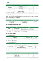
Tab. 4.2.1.4 Enclosure port
Environmental phenomena
Test specification
Basic standard
Acceptance
criteria
Radiated radiofrequency electro-
magnetic field
80-1000 MHz
IEC 61000-4-3
A
10 V / m (r.m.s.)
80% AM (1 kHz)
Electrostatic discharge
contact discharge
6 kV (charge voltage)
IEC 61000-4-2
B
air discharge
8 kV (charge voltage)
Power frequency magnetic field
50 Hz or 60 Hz frequency
IEC 61000-4-8
A
B
30 A (r.m.s.) / m - continuous
300 A (r.m.s.) / m - 1 to 3 s
4.3.
Product safety requirements
Voltage test of solid insulation and insulation resistance measurements for auxiliary power supply, inputs,
outputs, communication and measuring circuits:
Tab. 4.3.1 Product safety
Type of insulation test
Value
Basic standard
Dielectric voltage test 50 Hz or 60 Hz
2,2 kV/AC 1 minute or 3,1 kV/DC 1 minute
PN-EN 60255-27
Peak impulse voltage test
5 kV pulse 1,2/50 µs; 0,5 J
Insulation resistance
>100 MOhm 500 VDC
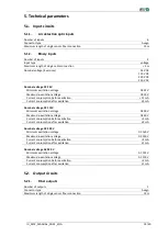
4.4.
Climatic environmental tests
Tab. 4.4.1 Climatic environmental test
Test
Standard
Description
Cold tests
PN-EN 60068-2-1:2009
Minimum operational temperature -20˚C/16 hours
Minimum storage temperature -55˚C/16 hours
Dry - heat tests
PN-EN 60068-2-2:2009
Maximum operational temperature +55˚C/16 hours
Maximum storage temperature +70˚C/16 hours
Damp - heat tests
PN-EN 60068-2-78:2013-11
+40˚C; 95% rh /10 days
4.5.
Mechanical tests
Tab. 4.5.1 Mechanical tests
Test
Standard
Class
Sinusoidal vibration
PN-EN 60255-21-1:1999
Klasa 1
Single and multiple shocks and bumps
PN-EN 60255-21-2:2000
Klasa 1
Seismic
PN-EN 60255-21-3:1999/Ap1:2002P
Klasa 0
4.6.
Degree of protection
Tab. 4.6.1 Degree of protection
Test
Description
Standard
Degree of protection
Degrees of protection provided by
enclosures (IP Code)
Front panel side without plugged fiber slots
PN-EN 60529:2003
IP 20
Front panel side with plugged fiber slots or
connected fibers
IP30
Connector side without connectors
IP 20
Connector side with connectors plugged
IP 30
4.7.
Installation requirements
Tab. 4.7.1 Installation requirements
Definition
Reguirements
Class equipment
2
Overvoltage category
III
Pollution degree
2
Electrical environment
B


