Programmer’s Guide
PcOS Series 80PLUS
Setting up the Printer
Rev B 4/13/99
Page 5
Chapter 2:
Setting up the Printer
Up to four cables can be connected to the printer, providing power, host interface, and cash drawer
support. They attach to the connector panel on the back of the printer, as shown below.
Interface
Cas h
Drawer 2
Power
Cas h
Drawer 1
Figure 1 Connector Panel
Connecting the Printer and Computer
You need an appropriate interface cable. The parallel interface requires a straight through 25-pin
connector, with male termination on the printer end, see the interface section for complete pin
definition details. The serial interface requires a DB25- to DB9-pin or DB9- to DB9-pin null modem
crossover cable, with a DB9-pin female terminal on the printer end, and the appropriate gender
connector at the host computer end. See the communication section for complete pin definition
details.
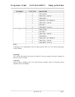
1.
Plug the cable connector securely into the printer’s interface connector.
2.
Tighten the screws on both sides of the cable connector.
3.
Attach the other end of the cable to the appropriate terminal on the computer.


