background image

27 

Starting the Instrument by Inserting a Cuvette  

1. 

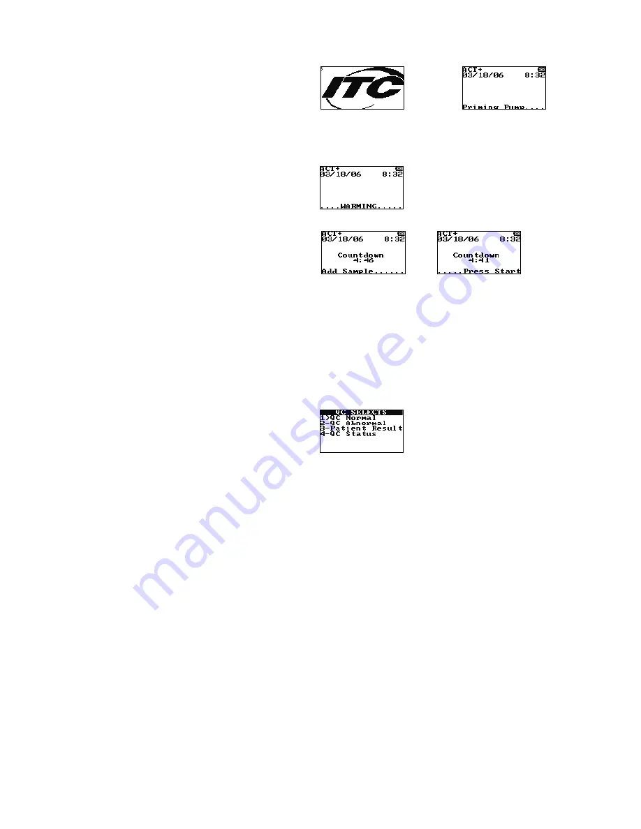
When a test cuvette (e.g., ACT+) is inserted to turn on the instrument, the following prompts are 
briefly displayed: 


(example only) 

followed by 


Note

:    The  test  name  for  the  inserted  cuvette  is  displayed  in  the  upper  left-hand  corner  of  the 

screen.    Check  the  display  for  fault  messages  while  the  cuvette  is  warming.  Refer  to  the 
Troubleshooting section for the procedure to resolve a fault message. 

2. 

The instrument then warms the cuvette to 37 °C ±1.0 °C: 


3. 

When the cuvette reaches temperature, the instrument beeps and alternately displays: 


    and    


4. 

The sample can now be added. After the sample is added, press 

START

 to run the test. 

RUNNING A TEST  

Samples are designated as patient samples by default. If a control is being run, the sample type must be 
changed from 

patient sample

 to 

QC Normal

 or 

QC Abnormal

. If a patient sample is being run, this step is 

unnecessary. 

Important

:  Failure to select 

QC Normal

 or 

QC Abnormal

 for a control sample will result in 

storage of the control results as patient results in the patient database. 

Designating the Sample as a Normal or Abnormal Control 

1. 

Press 

QC

 to display the QC SELECTS menu: 


Note:

 A cuvette must be inserted into the instrument to display the QC SELECTS menu. If entry of 

a  cuvette  lot  number  and/or  Operator  ID  or  PIN  is  required,  this  must  be  done  before  the  QC 
SELECTS menu can be displayed. 

2. 

Press 

1

 to designate the sample as a 

normal control

 (

QC Normal 

is displayed), or press 

2

 to 

designate the sample as an 

abnormal contro

l (

QC Abnormal 

is displayed). 

Note:

    The  sample  type  can  be  designated  either  before  or  during  the  test,  unless  QC  lockout 

features are enabled. Once 

QC

 is selected, pressing the 

QC

 key again briefly displays the QC level 

and assay being run.  

To exit the QC menu, press the CANCEL key.


Important:  Once a QC type is selected, it cannot be changed. 

Summary of Contents for HEMOCHRON Signature Elite

Page 1: ...ss at the back of this manual or to your ITC representative ITC HEMOCHRON and HEMOCHRON Signature Elite are registered trademarks of International Technidyne Corporation in the United States and other...

Page 2: ...rough the interaction of tissue factor with factor VII Platelets essential co factors in this reaction provide the platelet phospholipid surface on which coagulation reactions occur Activated Clotting...

Page 3: ...ette After mixing with the reagent the sample is moved back and forth at a predetermined rate within the test channel and monitored for clot formation The test channel is maintained at 37 C 1 0 C duri...

Page 4: ...Electronic Quality Control System Verification HCM HEMOCHRON Configuration Manager INR International Normalized Ratio idms Integrated Data Management System LQC Liquid Quality Control OID Operator Id...

Page 5: ...ner for reading of barcode labels Keypad The front panel contains a keypad with various action keys as well as a number pad The operator uses the keypad to select a command or enter information Action...

Page 6: ...currently stored in the instrument and the number of additional test results that can be stored Display results of the stored patient or QC tests Delete patient or QC records Initiate POCT 1A communi...

Page 7: ...e supervisor PIN at the prompt then press and hold the Enter key Print Options Menu Press the 6 key while the Supervisor Menu is displayed Communications Menu Press the 7 key while the Supervisor Menu...

Page 8: ...1 is displayed Database Menu Press the DATABASE key Execute a command on a menu by pressing the action key for that command For example if the Main menu is displayed press the 4 key to shut down the...

Page 9: ...seconds or INR test type is automatically read from the cuvette barcode or manual entry of identification numbers cuvette lot information and quality control lot information test results are automati...

Page 10: ...sound one short beep when pre warming is complete Test Timeout Incubation of a cuvette stops automatically if START is not pressed within five minutes after Add Sample and Press Start are displayed Au...

Page 11: ...refer to the back panel of the instrument to identify the class of laser and follow appropriate instructions provided in this manual 1 The barcode scanner contains an IEC 60825 1 class 1 or class 2 l...

Page 12: ...care Handle and open the container with care Expiration Date of Cuvettes Lot Number of Cuvettes Do Not Reuse Cuvettes Single Use Only Upper and Lower Temperature Limitations For Storage or Use Consult...

Page 13: ...terleaved 2 of 5 Discrete 2 of 5 Codabar and MSI Plessey Laser Class IEC 60825 1 class 1 or class 2 laser product complies with 21 CFR 1040 10 and 1040 11 except for deviations pursuant to Laser Notic...

Page 14: ...must obtain a power supply cord Materials Required But Not Provided Article Quantity HEMOCHRON Jr Test Cuvettes As Needed HEMOCHRON Jr Quality Control Products As Needed Optional Materials Article Qu...

Page 15: ...Charge Indicators A battery charge LED on the front panel page 5 is illuminated whenever the battery is being charged The LED flashes when the remaining battery power is low A battery charge status in...

Page 16: ...nd the entry is saved 6 Press CANCEL to return to normal operation Instrument Shutdown 1 Press 0 zero to display the main menu 2 Press 4 The instrument is shut down Note The instrument can also be shu...

Page 17: ...ress ENTER to save the new setting To Adjust the Display Brightness Display brightness can be set so the display background is darker or lighter 1 Press 2 to display the Brightness menu 2 Press 7 to d...

Page 18: ...oad the lot number expiration date and expected range for control materials to HEMOCHRON Configuration Manager Scan Operator IDs for uploading to HEMOCHRON Configuration Manager Set the instrument dat...

Page 19: ...nu press 2 to display the Scan OID screen 2 Position the scanner port of the instrument approximately four inches from the barcode see page 5 3 Press PRINT SCAN to scan the barcode The scanned Operato...

Page 20: ...ons Listings of cuvette lot numbers quality control lot numbers or Operator IDs can be printed at an external printer see page 25 for instructions to connect the printer 1 On the Supervisor menu press...

Page 21: ...r the network 1 From the Supervisor menu press 7 to display the Communications menu 2 Press 1 to select the desired communication protocol Display OFF to use the ITC proprietary communication protocol...

Page 22: ...splay Push POCT OFF Entering Network Communication Parameters Some or all of the following parameters may need to be entered in order for the instrument to communicate over a network IP Address Gatewa...

Page 23: ...evices This range of Auto IP addresses should not to be used over the Internet Auto IP can be disabled by setting the device s IP address to 000 000 001 000 This setting enables DHCP but disables Auto...

Page 24: ...rsonal Computer An experienced network administrator can communicate with the XPORT Setup module and enter communication parameters using a personal computer connected to the COM port 1 From the Super...

Page 25: ...e printer cable to the printer To Connect to a Personal Computer 1 Obtain a computer interface cable Note The computer interface cable is included with the instrument A replacement PCKIT Personal Comp...

Page 26: ...ng a cuvette Note Allow cuvettes to reach room temperature 15 to 30 C before opening the pouch This may take up to 60 minutes Consult the cuvette package insert for additional information concerning c...

Page 27: ...mal or QC Abnormal If a patient sample is being run this step is unnecessary Important Failure to select QC Normal or QC Abnormal for a control sample will result in storage of the control results as...

Page 28: ...n of 1 to 20 characters During PID entry a PID exceeding 16 characters will wrap to the next line The number of characters to be entered for PID from 1 to 20 may be designated via Configuration Manage...

Page 29: ...dvances Note The OID can be designated or changed anytime unless operator lockout is enabled through Configuration Manager Check the OID by pressing ID and then pressing 2 to display the entered value...

Page 30: ...n for entering the cuvette lot number Enter the cuvette lot number using the numeral keys Note Press the NOTE key to change from numeric to alphabetical characters or vice versa When alphabetic charac...

Page 31: ...e to scan the PID using the barcode scanner or to enter it manually 3 Press and hold ENTER If an acceptable PID is entered operation of the instrument continues followed by Note When running a test or...

Page 32: ...fic patient test s can be run If EQC is required no patient tests can be run until successful completion of EQC Note A specified limited number of additional tests per assay 911 exceptions can be run...

Page 33: ...controls is entered using Configuration Manager see page 65 Information for up to five lots of normal controls and five lots of abnormal controls can be stored for each assay type A control lot numbe...

Page 34: ...ght the second note field before typing a number for the second note Note No Note is displayed if a note is not defined for a note field To remove a currently entered note highlight the note field and...

Page 35: ...sed to transfer blood 2 Press the START key The elapsed time in seconds is displayed until the sample clots Note SAMPLE TOO SMALL SAMPLE TOO LARGE or SAMPLE NOT SEEN is displayed if an incorrect amoun...

Page 36: ...ample sensing LEDs are functioning properly and that the cuvette is adequately sealed If these instrument and sample parameters are not appropriate the test is terminated and an error message displaye...

Page 37: ...ain a cuvette for the test to be validated and insert it into the instrument 3 To run QC when it is not required press the QC key 4 Select QC NORMAL or QC ABNORMAL and enter an Operator ID optional fo...

Page 38: ...essive force in pressing the instrument keys DO NOT expose the instrument to extreme temperatures above 37 C DO NOT drop the instrument and do not use the results if the instrument is dropped during a...

Page 39: ...test results and 600 quality control test results can be stored in the instrument In addition to test results the date and time of each test PID OID and user notes are also stored Note PID and or OID...

Page 40: ...o display additional assays Enter the number for the assay then press ENTER All patient test results for the specified assay are printed e To print results for a specific cuvette lot number press 5 to...

Page 41: ...umber then press ENTER All QC test results for the specified cuvette lot number are printed e To print results for a specific control lot number press 5 to display the Print by QClot screen Scan or ty...

Page 42: ...rom alphabetical ABC shown above to numerical 123 or vice versa Note If alphabetic characters are being entered advance from the displayed letter to the next letter on that key by pressing the key aga...

Page 43: ...play Total Tests and Remaining Tests in the Database 1 Press 1 The total number of stored patient records and QC records plus the number of records that can still be added to the patient database and...

Page 44: ...he previous record To Initiate Communication When Using the POCT 1A Communication Protocol 1 Press 6 A confirmation is displayed when communication is established Note Refer to Communication with a PC...

Page 45: ...n Sample Not Seen STS Sample Too Small Sample Too Small STL Sample Too Large Sample Too Large TTO Temp Timeout Heater Too Cool TTH Temp Too High Heater Too Hot SPF Sample Position Fault Sample Pos Fau...

Page 46: ...rom the instrument 1 If necessary check the instrument Communications menu and verify that the POCT 1A communication protocol and the NET communication port are specified Note The Communications menu...

Page 47: ...t data transfer Status messages may be displayed on the instrument during initiation of communication and and confirmation is displayed when communication is established 3 Initiate data transfer at th...

Page 48: ...lation 4 A message will be displayed when the software is successfully loaded After the message is displayed remove the CD from the computer 5 Shut down and restart the computer if prompted to do so C...

Page 49: ...ration Manager software is run for the first time instructions are displayed to logon using the default user name and password a Click OK and then click Start Program The Logon dialog box is displayed...

Page 50: ...on from the Utilities menu d Click OK The information is saved and the User Master File Maintenance dialog box is displayed e To change the default Supervisor user password enter a new password Ensure...

Page 51: ...rint listings of configuration parameters instruments operators see page 68 and audit trail Master File Maintenance Display modify add and delete instrument information Utilities Rebuild and compress...

Page 52: ...is automatically detected and displayed Note Load the default HEMOCHRON Signature Elite settings by selecting Factory Default from the Configuration Revision drop down list These settings can be modi...

Page 53: ...o make the connection Note If the POCT 1A communication protocol is used specific messages indicate the progress of data transfer If the connection is not made the instrument will beep display Network...

Page 54: ...r until a new PID is entered 4 Specify that the barcode scanner must be used for entering the Patient ID d Date Format Options 1 Specify a date format of MM DD YY or YY MM DD e Time Format Options 1 S...

Page 55: ...ions dialog box Information concerning the configuration file is displayed Instrument General Options 1 Allow Date Time Change Enter a check mark to allow the operator to change the date and time on t...

Page 56: ...Enter a check mark to require entry of a PID when running a patient test 2 Patient ID Length Select the minimum from 1 to 20 and maximum from 1 to 20 number of digits that must be entered for a patien...

Page 57: ...or is prompted to scan the QC information when running a test The operator can still enter the QC information manually by pressing the 7 key as indicated by the 7 Manual Entry prompt but the QC inform...

Page 58: ...test for specifying lockout parameters Current settings for the test are displayed Note The number of patient tests that have already been run against the 911 override limit is displayed in the of 911...

Page 59: ...articular assay from being run enter a check mark in the QC Normal or Abnormal Required box enter a range and then enter 0 for the QC Interval The message DISALLOWED ASSAY REMOVE CUVETTE displays when...

Page 60: ...xceptions 1 Click Lock Out Control on the Configuration Module dialog box page 53 to display the QC Lockout dialog box 2 Select the QC Exceptions tab Note Entries made on the QC Exceptions tab apply t...

Page 61: ...king on Read Configuration from Instrument 1 After the configuration data from the instrument has been read select Clone Instrument The Clear Instrument Counts dialog box is displayed see page 67 2 Pl...

Page 62: ...Note If OIDs will be entered using the instrument keypad OIDs should contain only those letters numerals and or characters that can be entered using the 0 through 9 keys on the keypad Note An OID that...

Page 63: ...the dialog box Note Cancel removes the dialog box without saving changes Clear Current Page clears all information from the current page of the Operator Table Clear All clears all information from th...

Page 64: ...RON Signature Elite instrument when running a test are only saved to that particular test record and are not uploaded to Configuration Manager 1 Click Cuvette Lots on the Configuration Module dialog b...

Page 65: ...umber information may be scanned using the barcode scanner through the Supervisor menu and uploaded to Configuration Manager page 19 If needed the expected ranges can then be manually changed by the s...

Page 66: ...ter a file name and or revision for the configuration data to be saved To save the configuration data under a new file name enter a name for the new configuration file in the Configuration field and e...

Page 67: ...e POCT 1A communication protocol 4 Click OK to continue 5 The Write Configuration dialog box is displayed 6 Establish communication to the instrument as described on pages 46 and 47 Note If the instru...

Page 68: ...s can be displayed and printed The reports provide an audit trail for specific information from all configuration files or for all instruments stored in the database Specific Report Description Instru...

Page 69: ...u The Serial Number Master File Maintenance dialog box is displayed 2 Click Add to display a blank information form 3 Enter the serial number unit location and comment if desired The Date Manufactured...

Page 70: ...turn to the main window CONFIGURATION MANAGER UTILITIES The HEMOCHRON Configuration Manager Utilities allow supervisors to maintain the HCM database Function Description System Configuration Update in...

Page 71: ...supervisor level access 5 Click Save The new user record is saved Updating a User Record The supervisor can modify or delete a record for an existing user 1 Select Security from the Utilities menu The...

Page 72: ...The instrument must be connected to a COM port If the instrument is connected to a network the date and time must be set at the instrument as described on page 19 4 Click Start Progress information is...

Page 73: ...67 6 Click Start Progress information is displayed in the status line 7 A message box is displayed when writing of the configuration data is complete Click OK to acknowledge the message Purging Config...

Page 74: ...e Database 1 Select Convert HCM Data from Ver 1 0 or 2 0 from the Utilities menu The Convert HCM Data from Version 1 0 or 2 0 dialog box is displayed Note The source and destination paths are shown Th...

Page 75: ...ssages can be found in Acronyms for Error Messages on page 45 If needed contact ITC Technical Support by phone at 1 732 548 5700 by FAX at 1 732 548 9824 or by e mail at techsupport itcmed com Error M...

Page 76: ...r insufficient sample Repeat test with new cuvette Premature Sample Sample was detected at front detector before specified time period May occur if sample is added before pump priming sequence is comp...

Page 77: ...onfiguration Manager Supervisor needs to reconfigure instrument using HCM Cannot erase DB Erasing patient and or QC database is not allowed Supervisor needs to reconfigure instrument using HCM INR 0 8...

Page 78: ...page of the Print menu 3 Press 3 to test the scanner 4 Position the scanner port see page 5 approximately four inches from the barcode label that is shown below Note The barcode shown above is format...

Page 79: ...by error messages detailed in the section Troubleshooting For Class 2 Laser Instruments CAUTION CLASS 2 LASER RADIATION WHEN OPEN DO NOT STARE INTO THE BEAM Battery Care To optimize battery life it is...

Page 80: ...o Disturbance Characteristics Limits and Methods of Measurement EN 61326 Electrical Equipment for Measurement Control and Laboratory Use EMC Requirements Directives 89 336 EEC and as amended by 91 263...

Page 81: ...81 This page intentionally left blank...

Page 82: ...g computer 24 network 24 printer 24 custom header 41 cuvette 9 cuvette lot number entering 28 63 cuvette validation 36 definitions 4 deleting a user record 69 70 description features 9 overview 5 disa...

Page 83: ...system information 41 QC lot number entering 32 64 Quality Control electronic EQC 35 instrument performance 35 instrument temperature 35 liquid LQC 36 liquid controls 35 results management 38 printing...

Page 84: ...84 HX1101 0310...

Reviews: