iSYSTEM, March 2017
18/66
Trace Port PCB Design Guidelines
This section contains some guidelines, which should be considered during the target PCB design to ensure the
correct operation of the trace port (ETM, Nexus,…) and the external trace tool (iC5500, iTRACE GT). Note that
the quality and timing of the trace port signals to the external trace tool are critical for correct and reliable trace
operation.
All trace port lines on the PCB should be as short as possible (max ~2,5 cm),
Traces should run on the same layer, or layers with the same impedance.
Preferred layer impedance is 50 Ohm.
Connector’s ground pins should be connected directly to PCB’s GND plane.
Trace clock should be serially terminated by 47 Ohm resistor as close as possible to the driver. The
value of the resistor may be changed depending on driver characteristics.
Trace clock should be clean of crosstalk – if possible with double distance to closest nets.
Trace clock should have only point-to-point connection – any stubs should be avoided.
It is strongly recommended also for other (data) lines to be point-to-point only. If any stubs are needed,
they should be as short as possible, when longer are required, there should be a possibility to optionally
disconnect them (e.g. by jumpers).
Trace port data bus inner crosstalk is not so important, but it is critical to isolate the whole bus from
other signals (including from the trace port clock).
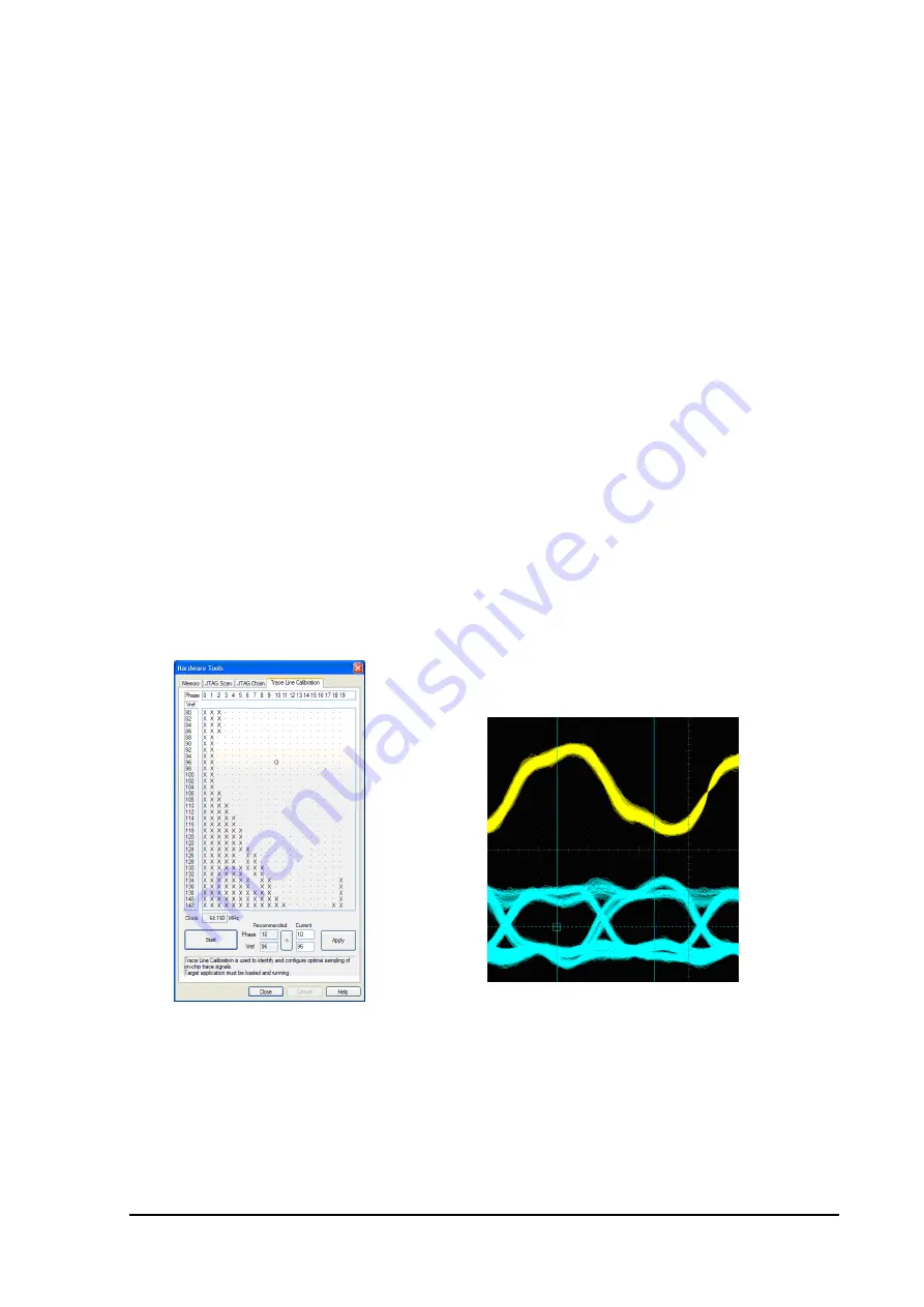
The following examples show, how the length of the trace lines is reflected in signal integrity and consequently
in functionality. One of typical evaluation boards was used, where the CPU is located on the upper piggyback
board, which fits to the lower, larger measurement board.
Trace lines with short stubs
Trace Line Calibration result
Measured by oscilloscope
Trace lines with longer stubs (over connector to other board)


