37
DM 54 Chimney System: Brick Ledge Installation
FIGURE 64
Consult local structural engineer for proper job-spe-
cific support structure design, sizing and load bearing specifi
-
cations.
If short lengths of steel rods are used be sure to properly
lap and wire tie all splices in the rebar. As the reinforcing pro
-
gresses, completely fill the holes with grout. Suitable grout can
be a pourable mixture of Portland cement and sand or Portland
cement, sand and pea gravel. The rebar must be fully embedded in
grout.
Leave enough of the #4 steel reinforcing rod exposed
above the brickledge so that as the stacking of outer casing blocks
continues to termination the reinforcing rods and grout can con-
tinue through the stack. Reinforcing shall continue to chimney
termination.
All DM 54 chimneys that include the DM 54 brickledge
must be reinforced as described above.
CAUTION:
When using the Isokern brickledge it is required that
the Fire-Lite firebox/smoke dome assembly include the placement
of a 4” by 4” by 3/8” minimum steel angle across the firebox
opening. (See page 41 for “Structural Information” for details
regarding specification and placement of steel angles in Fire-Lite
fireplaces.)
Lateral Support for Isokern Brickledge Chimneys:
Once the DM 54 chimney and brickledge are assembled
and after the intended masonry veneer has been installed on the
brickledge, be sure to brace the chimney following the guidelines
on pages 31 & 32 of this manual for Lateral Support of DM 54
chimneys.
Summary of Contents for FIRE-LITE series
Page 7: ...Assembled Firebox Smoke Dome Dimensions 36 42 46 7 ...
Page 23: ...23 Interior Masonry Veneer Fireplace Finishes Clearances FIGURE 38 FIGURE 36 FIGURE 37 ...
Page 28: ...DM 54 Chimney Component List Dimensions 28 ...
Page 32: ...32 DM 54 Chimney System Lateral Support cont FIGURE 51 FIGURE 52 ...
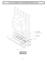
Page 51: ...51 Fire Lite Application Raised Metal Platform cont FIGURE 93 ...
Page 58: ...Notes 58 ...


