background image

49


Floor framing for a Fire-Lite installation will need to 

be designed and built to accept substantial dead loads spread 

over a relatively small floor area.


The following weights and sizes can be used to cal

-

culate Fire-Lite loading. Consult with local structural engineer 

for proper sizing of structural floor frame members for specific 

installations.

Load Calculations: 


Total dead load amounts include (but are not neces-

sarily limited to) the following items and their corresponding 

weight estimates listed below:

1. Fire-Lite unit model weights:

a. Model 36 FP: 1205 lbs.

b. Model 42 FP: 1325 lbs.

c. Model 46 FP: 1450 lbs.

2. Damper, fire brick and mortar: 450 lbs.

3. Raised platform: 40 lbs.

4. Fireplace finished facing: approx. 200 lbs.

5. Weight of metal flue: negligible


By adding the weight of the appropriate Fire-Lite 

Model listed in #1 above to the allowance given for each item 

in 2 through 5, above, the total weight of the Fire-Lite Series 

can be estimated.

Total approximate Fire-Lite Series weight estimates for 

each Model:

Model 36 FP @ 1205 lbs + items 2 thru 5 @ 690 = 1895 lbs.

Model 42 FP @ 1325 lbs + items 2 thru 5 @ 690 = 2015 lbs.

Model 46 FP @ 1450 lbs + items 2 thru 5 @ 690 = 2140 lbs.

The floor area for each model is as follows:

Model 36 FP @ 43” x 25.25” = 7.54 sq.ft.

Model 42 FP @ 48.5” x 25.25”= 8.50 sq.ft.

Model 46 FP @ 53” x 25.25” = 9.30 sq.ft.

Notes:


These dead load totals are in addition to the live load 

and other dead load requirements for the specific site’s pro

-

posed floor.


The load estimates given above for items are esti-

mates only and may not accurately define total loads related 

to the completed fireplace due to material choices that are at 

owner option.


Consult your local structural engineer for proper floor 

system design, sizing and specifications.


Isokern is not responsible for structural floor support 

details for the Fire-Lite fireplace. Unless otherwise noted all 

floor framing drawings in this manual are merely illustrations 

to indicate the presence of an underlying floor system.

Fire-Lite Application - Combustible Floor System

FIGURE 89

FIGURE 90

Summary of Contents for FIRE-LITE series

Page 1: ...ps guidelines use and maintenance in structions for the Fire Lite application fireplace with the FTF 13 Chimney System This manual must be come the property of and be reviewed by all current and future users of this product It is the responsibility of the general contractor and the installer of this product to ensure that the instructions in this manual are followed exactly and further that any al...

Page 2: ...ance to Combustible Trim Concrete Support DM Chimney System General Information Component List Dimensions Component Weights Installation Lateral Support Offset Block Brick Ledge Installation Brick Ledge Load Capacity Crown Caps Height Requirements Structural Information Wind Loads Common Chimney Terminations Class A Metal Flue Specialty Applications See Thru Two Story Stacked Installations Fire Li...

Page 3: ...The Fire Lite fireplace is available in many sizes The Standard series 36 42 46 and the Magnum sizes 28 36 42 48 The various Fire Lite fireplace and DM 54 chimney components will be described and illustrated in the following pages Close attention should be paid to each component group s specifications and installation requirements as described in this manual Intended Use Statement The Fire Lite is...

Page 4: ...gs Illustrationsinthismanualare not to scale and are intended to show typical installations Nominal dimensions are given for design and framing reference only since actual installations may vary due to job specific design preferences Always maintain the stated minimum clearances to combustible materials Do not violate any specific installation requirements The Fire Lite has been tested and listed ...

Page 5: ...s of air during the normal firing process In the event the home is tightly sealed and has modern energy efficient features the optional combustion air supply kits may not provide all the air required to support combustion and the proper flow of combustion gases up the chimney The manufacturer is not responsible for any smoking or related problems that may result from the lack of adequate air suppl...

Page 6: ...le for use with solid fuel or listed gas appliances Refer to the manufacturer s installation manual for detailed description of clearances to combustibles and all other installation information A metal listing label similar to that shown above is affixed to each Fire Lite Series fireplace Do not remove the listing label from the Fire Lite Series fireplace Prior to beginning installation contact yo...

Page 7: ...Assembled Firebox Smoke Dome Dimensions 36 42 46 7 ...

Page 8: ...ons 36 42 46 8 Isokern reserves the right to make changes at any time without notice in design materials and specifications and also to discon tinue styles and products Please call 800 642 2920 for an Isokern dealer near you ...

Page 9: ...minimum of forty eight inches 48 from the fireplace opening Notes 1 The Fire Lite Application is designed tested and approved for installation at a minimum of Four inches 4 above combustible floor systems per the installation specifications given in this manual Any portion of the combustible floor system left exposed under the base plate is to be covered with min 1 thick ceramic fiber insulation b...

Page 10: ...of a Fire Lite fireplace in a corner condition where the DM 54 chimney must turn 45 degrees to align with overhead framing Firebox A B C D Standard Series Model 36 43 49 35 72 Model 42 49 52 37 75 Model 46 53 54 39 79 Magnum Series Model 28 33 1 2 18 1 4 24 65 1 2 Model 36 43 16 3 4 32 78 3 4 Model 42 49 26 1 2 36 83 Model 48 53 28 1 2 39 85 3 4 Model 60 73 1 2 39 53 1 2 102 1 2 Model 72 85 1 2 45...

Page 11: ...gligible By adding the weight of the appropriate Fire Lite Model listed in 1 above to the allowance given for each item in 2 through 4 above the total weight of the Fire Lite Series can be estimated The floor area for each model is as follows Model 36 Standard Series 43 x 25 25 7 54 sq ft Model 42 Standard Series 49 x 25 25 8 59 sq ft Model 46 Standard Series 53 x 25 25 9 29 sq ft Model 28 Magnum ...

Page 12: ...f inch 1 2 beads of the Earthcore Mortar to the area to assure proper sealing of the joint Properly mortared firebox and smoke dome assembly requires approximately 5 gallons dry measure of Earthcore Mortar Step 1 Set the Fire Lite base with Earthcore Mortar flat on a proper support foundation allowing 1 1 2 clearance to combustible framing from the sides and rear of the firebox Do not set the Fire...

Page 13: ...he side walls and back wall are to sit By doing this the first layer of wall components can be set directly into mortar already applied to the proper areas on the base plate Be sure to put Earthcore Mortar on the contact surfaces of the vertical joints where the side wall and back wall components connect Figure 15 Broken Components Components broken into 2 or 3 pieces can be repaired by using Eart...

Page 14: ...ase plate Step 6 Begin the smoke dome assembly by setting the rear bottomsmokedomecomponentontopofthebackwallassembly in a bed of Earthcore Mortar The Fire Lite back wall assembly should sit flush with the backside of the Firebox Figure 19 Step 7 Set the cast iron throat damper on top of the damper lifter blocks so that the damper s operating plate is up and faces the back of the firebox Figure 20...

Page 15: ...on The sleeve passes through the firebox wall and must be connected to metal pipe by other either flexible or rigid that leads to the source for outside combustion air as directly as possible from the Fire Lite Fireplace Few to no bends with a maximum length of sixty feet 60 WARNING Do not use combustible duct material Avoid installing a combustion air inlet where the opening could be blocked by s...

Page 16: ... 8 give a good appearance to the finished brickwork however this is just a suggestion and other face joint dimensions are also acceptable Step 1 Wet mop the inside of the Fire Lite fireplace with a damp sponge to remove dust and loose particles from the inte rior before installing fire brick Step 2 Start the fire brick at the front edge of the floor of the Isokern firebox proceeding inward toward ...

Page 17: ...of the firebox and smoke dome Figure 24 Drywall can be hung on the framing members and pass across the face of the smoke dome and in contact with it If necessary the drywall can be affixed to the face of the Fire Lite Series fireplace with drywall screws maximum length 1 do not use nails The drywall must be cut back a minimum of 2 from the sides of the firebox opening and 8 back from the top of th...

Page 18: ...jury or loss of life The manufacturer is not responsible for installation and use practices that are beyond the scope of the product as defined in the product listing and in the installation manual WARNING Do not pack or fill the air spaces with insulation or other material No material is allowed in these areas The manufacturer strongly recommends that wherever possible all combustible framing mat...

Page 19: ...ed directly to the front face of the Isokern fireplace unit be sure that when the required noncombustible finished facing materials are applied that no gaps or voids are left behind the finished facing materials Completely seal the required noncombustible finished facing materials directly to the Isokern unit with Earthcore mortar or other noncombustible grout 19 Required Clearance to Combustible ...

Page 20: ...e surfaces Figure 33 When Fire Lite fireplace installations are surrounded by walls that are to be insulated the walls must have enough clearance to the Isokern unit in order to maintain the three inch 3 minimum clearance to insulation Figure 33 Never spray the Fire Lite fireplace with any type of sealer insulation or other material If insulation or vapor barriers are used in walls surrounding the...

Page 21: ...gh firebox front This will aid in the overall fit and finish of the Fire Lite fireplace front when the code required noncombustible finished facings are applied This alignment of fire brick application as shown above Figure 34 allows the fire brick lining to be in the same plane with the room s wall finish surface With the fire brick set in this fashion the noncombustible finish facing material ca...

Page 22: ...inish facing material set across the top of the firebox opening Figure 35 WARNING Avoid false chimneys Important Failure to seal any gaps between the front face of the Fire Lite damper plate and the back of the noncombustible finished facing material will create what is known as a false chimney A false chimney in this case is the narrow gap mentioned above between the back of the noncombustible fa...

Page 23: ...23 Interior Masonry Veneer Fireplace Finishes Clearances FIGURE 38 FIGURE 36 FIGURE 37 ...

Page 24: ...mini mum four inch 4 end bearing This bearing surface area shall be provided in the veneer work Figure 39 It is important that the steel L is set tight against the Fire Lite s damper beam front and set in a mud joint to avoid creating a false chimney be tween the back of the steel L and the Fire Lite s damper beam front Figure 40 Steel L or angle used to support masonry veneer as it spans the Fire...

Page 25: ...rom the face of the fireplace shall have additional clearance from the eight inches 8 equal to the projection Combustible projecting mantles up to twelve inches 12 of projection shall not be placed less than fouteen inches 14 from the top of the fireplace opening Combustible mantles which project more than twelve inches 12 from the face of the fireplace shall have additional clear ance from the fo...

Page 26: ...ulti floor and back to back installations proper weight computation on an individual basis is required Consult local structural engineer for load bearing requirements Important Foundations and footings must meet local code and be approved by the local building authority For any foundation design and load requirements check with local structural engineer It is the responsi bility of the General con...

Page 27: ...erever a chimney passes between one zone of a building to another Ex When the chimney passes through the ceiling into the attic area there must be a sealed area around the chim ney so there isn t a chaseway for a re to get to the attic Since lateral support is required for DM 54 chimneys the framing members will be in contact with the DM 54 chimney system Important Combustibles are defined as norm...

Page 28: ...DM 54 Chimney Component List Dimensions 28 ...

Page 29: ...f the firebox and smoke dome Additional reinforced concrete footing and slab area may need to be provided adjacent to or as a continuation of the primary support slab area for bearing the steel or masonry support required for an offset sequence Notes Plan chimney configuration carefully before construct ing the required reinforced concrete support foundation for the Fire Lite fireplace Be sure tha...

Page 30: ... aligns with the flue hole in the smoke dome lid Next set the DM 54 inner liner s six inch 6 tall starter piece Figure 48 inside the first outer casing block The factory version of the six inch 6 tall inner liner starter piece has a female end and a flat end Set this inner liner starter with the flat end down Set the downward end into Earthcore Mortar so that it is fully sealed to the smoke dome l...

Page 31: ...trap or equal Starting on one side of the DM 54 chimney at four foot 4 intervals up the structural wall adjoining the chim ney connect one 18 gauage strap tie to the structural wall with two three inch 3 8 minimum wood screws or masonry anchors as appropriate Next fold the strap around the three exposed sides of the DM 54 Connect the strap to each of the three DM 54 faces with two one and one half...

Page 32: ...32 DM 54 Chimney System Lateral Support cont FIGURE 51 FIGURE 52 ...

Page 33: ...he interior flue alignment as each offset block is set to avoid creating overhanging ledges on the inside of the flue Such internal overhangs will inhibit flue drafting Each offset block is to be set fully in a bed of Earthcore Mortar completely sealing each offset block to the underlying component Offset chimney block sequences can be built to shift the chimney run to the left right or to the rea...

Page 34: ...This allows for the smoke dome to sit flush with the inside face of the 2 by 6 wall and the straight chimney to run up the outside of the wall Figure 56 For a wall thickness of 9 nominal 8 CMU plus 1 1 2 furring strip first set two offset chimney blocks in sequence rearward This leaves a distance of 9 3 4 from the front face of the smoke dome to the front face of the DM 54 outer casing once the ou...

Page 35: ...ence will require When establishing the far face of the overhead obstruction be sure that the DM 54 chimney blocks can run straight to chimney termination without further overhead obstruction since a second offset sequence is not allowed Figure 60 Be sure that there is sufficient space beyond the far face of the overhead obstruction to accept the DM 54 chimney s outer casing dimension of 21 1 2 Su...

Page 36: ...along the length of the rafter where the chimney is to penetrate the roof line will increase above 34 relative to the pitch of the roof As the DM 54 outer casing and inner liner assembly approaches the roof penetration set an outer casing block to a level of approximately 6 below the low side of the roof framing Figure 64 The alignment tongues on the top of this outer cas ing block must be ground ...

Page 37: ...o termination the reinforcing rods and grout can con tinue through the stack Reinforcing shall continue to chimney termination All DM 54 chimneys that include the DM 54 brickledge must be reinforced as described above CAUTION When using the Isokern brickledge it is required that the Fire Lite firebox smoke dome assembly include the placement of a 4 by 4 by 3 8 minimum steel angle across the firebo...

Page 38: ...uld govern weather proofing details and the placement of flashings A typical flashing detail would be to field fabricate an aluminum or galvanized sheet metal flashing approximately thirty two inches 32 square with a twenty inch 20 square hole in it to serve as an inner flashing Figure 65 Place the inner flashing on the first DM 54 outer cas ing block that fully clears the roof line Keep the flash...

Page 39: ...t do not require the installation of the Isokern brickledge The small crown cap is also suitable where DM 54 chimneys are to receive a stucco finish Other chimney terminations are possible with DM 54 chimneys Check local codes for use of custom chimney terminations and decorative shrouds DM 54 Large Crown Cap Figure 68 The DM 54 large crown cap is a prefabricated ce ment weather cap for masonry ve...

Page 40: ...s adjoining roof lines adverse wind conditions etc may require a taller chimney for the fireplace to draft properly Chase Enclosures DM 54 chimneys can be enclosed within a wood framed chase at zero clearance to wood framing members Chase enclosures need to be built to local wind load require ments and shall be structurally independent of the Isokern chimney As with all chimney installations avoid...

Page 41: ...ortant The application of the steel angle as described above is also required in all Fire Lite installations where the brickledge is used This required steel lintel placement is in addition to the reinforcing required for DM 54 chimneys with brickledge as described on page 37 Important For DM 54 chimneys with both offsets and a brickledge it is important to fully support the last offset block wher...

Page 42: ...ys Due to owner preference and architectural design criteria other chimney terminations can be used alone or in conjunction with the crown caps Special design caps may be designed and constructed by others and must be fashioned so as not to restrict the flow of smoke and gasses out the top of the flue opening Figure 75 depicts common chimney termina tions Check with local building codes to establi...

Page 43: ... to UL 103 ULC S629 2 Double wall with solid pack insulation 3 A combination of double wall solid pack insulation and air space triple wall 4 Triple wall air space solid fuel chimney 5 Listed chimney liners conforming with the seventeen hundred degree 1700 Fahrenheit requirements of UL 1777 or ULCS635 or ULC640 may also be used with Isokern fireplaces Notes The selected approved chimney manufactur...

Page 44: ...y is complete it is necessary to place a steel angle minimum 4 x4 x3 8 across each face of the two sided opening before building the smoke dome assembly Notch the ends of each sidewall equal to the thickness of the steel as shown Each end of the steel angles must bear fully at least 3 onto the side wall assembly Figure 80 Since there is no back wall assembly and no side wall ledge for placement of...

Page 45: ... its chimney to rise at a thirty degree 30 angle of offset maximum angle of offset as allowed by code and bypass to one side of the firebox in the upper location there are minimum required floor to floor height dimensions See chart page 54 Dimension F The minimum floor to floor height required for an installation is determined by calculating the total horizontal distance the lower flue must travel...

Page 46: ...g wall for the upper unit s support slab D is the outside to outside dimension of the two eight inch 8 thick bearing walls underpinning the upper unit s support slab D is also the width of the upper unit s support slab and includes the ad ditional space for the width of the DM 54 chimney as it bypasses the upper unit D is also the sum of B plus C E is the height of the Fire Lite fireplace chosen f...

Page 47: ...the same as stated on page 5 of this manual Do not scale drawings Illustrations in this manual are not to scale and are intended to show typical installations Nominal dimensions are given for design and framing ref erence only since actual installations may vary due to job specific design preferences Always maintain the stated mini mum clearances to combustible materials Do not violate any specifi...

Page 48: ...ch 0 clearance All combustible sheathing materials must be held eight inches 8 away from the sides of the firebox opening and eight inches 8 above the top of the firebox opening Drywall must be cut two inches 2 back from the firebox open ing sides and eight inches 8 above the top of the opening CAUTION Maintain a minimum of three inch 3 clearance to insulation and vapor barriers Figure 33 page 20 ...

Page 49: ... Lite Series can be estimated Total approximate Fire Lite Series weight estimates for each Model Model 36 FP 1205 lbs items 2 thru 5 690 1895 lbs Model 42 FP 1325 lbs items 2 thru 5 690 2015 lbs Model 46 FP 1450 lbs items 2 thru 5 690 2140 lbs The floor area for each model is as follows Model 36 FP 43 x 25 25 7 54 sq ft Model 42 FP 48 5 x 25 25 8 50 sq ft Model 46 FP 53 x 25 25 9 30 sq ft Notes Th...

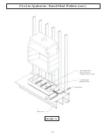
Page 50: ...es 2 beyond the ends of the raised platform Any overlaps in the length of the safety strips should be a minimum of two inches 2 for continual coverage of the combustible floor at the front of the fireplace Figure 92 The exposed combustible floor within the perimeter formed by the noncombustible raised platform must be completely covered with one inch thick ceramic fiber insulation board Figure 90 ...

Page 51: ...51 Fire Lite Application Raised Metal Platform cont FIGURE 93 ...

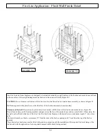
Page 52: ... can be placed directly in contact with the front of the firebox and smoke dome Figure 94 Drywall can be hung on the framing members and pass across the face of the smoke dome and in contact with it If necessary the drywall can be affixed to the face of the Fire Lite Fire Lite Series fireplace with drywall screws maximum length 1 do not use nails The drywall must be cut back a minimum of 2 from th...

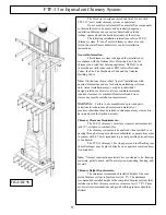
Page 53: ...imum required clearances to combustible materials and do not violate any specific installation requirements WARNING Failure to use manufacture s provided parts variations in techniques and construction materials or practices other than those described in this manual may create a fire hazard and void the limited warranty Chimney Clearance Requirements The FTF 13 chimney s outer layer requires a min...

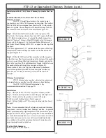
Page 54: ...ure blanket is held between the anchor plate and the top plate as a gasket Figure 99 Attach Anchor Plate to the top plate with masonry attachment screws through holes provided in the anchor plate into the top plate Do not over torque masonry screws into the Fire Lite material Chimney Terminations FTF 13 chimney pipe requires a termination component to be installed at or near the top of the chimney...

Page 55: ...55 FTF 13 Installation Components Round Termination FireStop Spacer Chimney Section Stabilizer Locking Band Anchor Plate Combination Offset Return Elbow FireStop Spacer 30 Offset Return Package 30 ...

Page 56: ...ow the first fire The second fire should be the same as the first fire The second fire should burn for no more than thirty to sixty minutes and allowed to go out Do not refuel the fireplace during the second lighting A twenty four hour cooling off period must be observed following second lighting After first and second fire continue use of the unit with three or four small fires of short duration ...

Page 57: ...ating season in colder climates thoroughly inspect the Fire Lite fireplace and chimney system Chimneys must be installed so that access is provided for inspection and cleaning The chimney should be inspected monthly during the heating season Inspect the entire flue from the top down for obstruc tions such as birds nests leaves etc Such obstructions must be removed Check spark arrestor screens for ...

Page 58: ...Notes 58 ...

Page 59: ...thereof is not responsible for any labor costs or indirect costs incurred for the replacement of defective components ISOKERN is not responsible for misuse or mishandling of components Nothing in this warranty makes ISOKERN or any division thereof liable in any respect for any injury or damage to the building or struc ture in which the fireplace or chimney system has been installed or to persons o...

Reviews: