24
5. Maintenance
Do not attempt to repair this Instrument. It contains no user-serviceable parts. Repair or servicing should only be performed by qualified personnel.
This instrument should be calibrated yearly, or more frequently if used in harsh conditions or if it is suspected of being inaccurate.
Cleaning
Periodically wipe the case with a damp cloth and detergent. Do not use abrasives or solvents.
5.1 battery Installation or Replacement
WaRNING:
To avoid electric shock, remove the test leads and power cable before replacing the batteries.
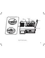
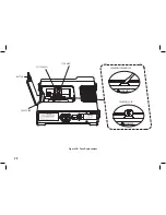
Refer to figure 3a and use the following procedure to replace the batteries.
1. Disconnect the test leads from any circuit under test and remove them from the instrument. Turn the ON / OFF switch on the rear panel to off and
remove the mains power lead from the instrument.
2. Use a finger or thumb to release the catch on the accessory compartment and open the cover. Remove any stored accessories.
3. Use a slotted screwdriver or other appropriate tool to release the catch on the battery cover at the rear of the compartment and remove the cover.
Retain the cover.
4. Disconnect the battery connector clip and remove the battery holder from the battery compartment. Retain the battery holder.
5. Remove the exhausted batteries from the battery holder and replace them with new ones. Observe the correct polarity as marked on the battery
holder. Do not mix batteries of different types or old and new batteries.
6. Reconnect the battery connector clip and refit the battery holder into the battery compartment.
7. Refit the battery compartment cover removed in para. 3 above.
8. Replace the accessories removed in para. 2 above.
9. Close the accessory compartment cover.
10. Turn the instrument on and check for correct operation.
11. Dispose of the removed batteries in accordance with local regulations.
Summary of Contents for IDM201N
Page 1: ...Instruction Manual IDM201N Digital Multimeter EN ES FR ...
Page 3: ...3 SECTION 1 SAFETY INFORMATION ...
Page 6: ...6 ...
Page 7: ...7 SECTION 2 INTRODUCTION ...
Page 9: ...9 SECTION 3 SPECIFICATIONS ...
Page 15: ...15 SECTION 4 OPERATION ...
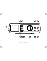
Page 18: ...18 Figure 1 Controls and Connectors 10 11 9 8 7 4 5 3 2 1 6 ...
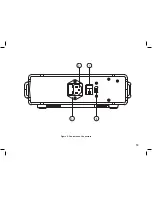
Page 19: ...19 Figure 2 Controls and Connectors 3 4 2 1 ...
Page 23: ...23 SECTION 5 MAINTENANCE ...
Page 29: ...29 Figure 3C Carrying Strap Attachment ...
Page 30: ...30 ...
Page 32: ......


