


16
4.0 setting Up The Instrument
Connecting to the Mains power supply
CaUTIoN:
To avoid instrument damage, check the rear-panel voltage selection switch is set to the Mains power supply voltage in your area
(see below)
Mains supply voltage:
switch setting:
90 to 132V, 50/60 Hz±
198 to 264V, 50/60 Hz
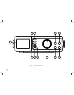
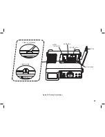
4.1 Controls and Connectors
see figure 1 for location of controls and connectors of the front panel.
1. Digital Display:
The digital display has a 3-1/2 digit LCD readout (maximum reading 2000), with auto polarity, decimal point,
overrange, AC/DC, Ω / ,
, MAX.MIN. and units indicators.
2. Rotary switch:
Select the Function and Range as required.
3. CoM Input Terminal:
Ground input connector.
4. VΩHz
Input Terminal:
Positive input connector for Volts, Ohms and Diode test, Capacitance and Frequency measurements.
5. ma Input Terminal:
Positive input connector for low-current measurement.
6. a Input Terminal:
Positive input connector for high-current measurement. The instrument can measure up to 20A. Maximum measurement duration
is 30 seconds in any 10 minute period for currents greater than 10A.
7. back light:
Press the yellow button to toggle the LCD backlight on or off.
8. Hold button:
Press the HOLD button to toggle the Data Hold mode on or off. In the Data Hold mode, the annunciator is displayed and the display
is frozen. When the hold button is pressed the beeper emits a tone and the value being read is held on the display. In the MIN MAX
Recording mode, press the Hold button to freeze the readings. Press the Hold button again to release the hold function for
normal recording.
Summary of Contents for IDM201N
Page 1: ...Instruction Manual IDM201N Digital Multimeter EN ES FR ...
Page 3: ...3 SECTION 1 SAFETY INFORMATION ...
Page 6: ...6 ...
Page 7: ...7 SECTION 2 INTRODUCTION ...
Page 9: ...9 SECTION 3 SPECIFICATIONS ...
Page 15: ...15 SECTION 4 OPERATION ...
Page 18: ...18 Figure 1 Controls and Connectors 10 11 9 8 7 4 5 3 2 1 6 ...
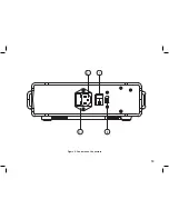
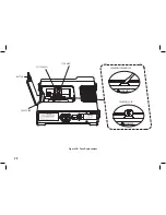
Page 19: ...19 Figure 2 Controls and Connectors 3 4 2 1 ...
Page 23: ...23 SECTION 5 MAINTENANCE ...
Page 29: ...29 Figure 3C Carrying Strap Attachment ...
Page 30: ...30 ...
Page 32: ......


