background image


ICP 4030 iMC-P 


11

/71


January 
2018 


11. The cutting machine may only be operated with original accessories, or accessories 

approved  by  the  manufacturer.  When  replacing  parts  in  accordance  with  these 
operating instructions, only original parts may be used. No liability shall be accepted 
for damages caused by the use of non-approved accessories or external parts. 

12. The cutting machine must not be used potentially explosive areas. 
13. When laying the mains line, make sure there are no risks of tripping or damage to 

the lines. 

14. If, without the written consent of the manufacturer, a change to the CNC machine 

or its components is made, the EC declaration of conformity issued shall become 
invalid. 

15. When cleaning the machine, avoid breathing in any dust created. 
16. Clean the machine only with suitable cleaning agents (standard household, non-

abrasive cleaning agents). 

17. Mobile telephones should not be used in the vicinity of the machine. Interference 

with the CNC control cannot be ruled out. 

Summary of Contents for ICP 4030 iMC-P

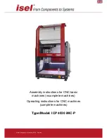
Page 1: ...Assembly instructions for CNC basic machines incomplete machines Operating instructions for CNC machines complete machines Type Model ICP 4030 iMC P isel Germany AG January 2018 German ...

Page 2: ...f not followed may result in damage or malfunction Information This symbol highlights important information and notices Safety notice Before you start up the CNC machine ICP 4030 work with the machine or make additions or changes to the electrical installation of the machine in the control cabinet 5 of the machine please read carefully the safety notices in these operating instructions Section 3 a...

Page 3: ...inery For all other machine parts and components to which CE safety guidelines apply start up is prohibited until all appropriate requirements are met The company isel Germany AG accepts no responsibility or liability if you make changes to the machine without the manufacturer s consent which affect the CE conformity of the machine The EMC test is only valid for the original machine configuration ...

Page 4: ...machine 17 4 7 1 Protective cover with solenoid interlock 18 5 Design and operation 19 5 1 Safety notices 19 5 2 Overview 20 5 3 Connections 21 5 3 1 Connections on the back 21 5 3 2 Front Panel Controls 22 5 3 3 Structure of the stepper motor control 23 5 4 Connections on the stepper motor controller 24 5 4 1 Safety notices 24 5 4 2 Access to the stepper motor controller and its components 24 5 4...

Page 5: ... linear axes X Y and Z 46 7 3 Maintenance intervals according to operating hours counter 48 7 4 Maintenance activities 49 8 Returning used electrical and electronic equipment for disposal 50 9 Remote diagnosis 51 10 Accessories 52 11 Technical Data 53 11 1 Dimensions and weight 53 11 2 Electrical Data 53 12 Malfunctions 54 13 Declaration of conformity or declaration of incorporation 55 13 1 Declar...

Page 6: ...efore delivery tested for many hours in depth measured at the factory and run in For each basic machine machine delivered a measurement and test report with the customer s order number is kept at the manufacturer isel Germany AG and can be requested by you as a buyer All basic machines machines are measured with circularity tester QC20 by Renishaw in all three interpolation planes or laser interfe...

Page 7: ...other manuals and instructions These are indicated in the source directory Example CNC basic machine ICP 4030 partly completed machine without tool no clear definition of the intended purpose this CNC machine is delivered without a CE mark the declaration of incorporation applies to this CNC machine Fig 1 ICP 4030 EC CNC basic machine Example CNC basic machine ICP 4030 Complete machine fitted with...

Page 8: ...lied human or animal effort consisting of linked parts or components at least one of which moves and which are joined together for a specific application Every isel CNC machine delivered with a tool e g cutter or engraving spindle dosing unit sensor like CCD camera or triangulation laser water jet nozzle plasma burner or equiv is a machine pursuant to the Machinery Directive 2006 42 EC because it ...

Page 9: ...cordingly based on the type of the tool fitted on the machine This means the concrete tool of the CNC machine determines the proper use of the machine in accordance with the Machinery Directive Annex I Section 1 1 2 Under this premise the CNC machine is suitable for milling drilling cutting engraving dosing measuring or water jet cutting The CNC machine is not suitable for graphite machining o Sui...

Page 10: ...r shall not exceed 7mm The rapid traverse rates should depending on the system size not exceed the value of 150 mm sec to a maximum of 200mm sec The feed speed of the tools in the material must be determined technologically and should always be less than the rapid traverse rate The user is responsible for the secure clamping of the tools in the tool holder The reasonably foreseeable misuse include...

Page 11: ...e damage to the machine or components In this case the manufacturer excludes any liability 4 Before starting the machine check that mains voltage specified on the rating plate of the individual components mains voltage matches the mains voltage available The wrong mains voltage can destroy the machine and its components 5 To prevent electric shocks do not put any objects into the machine an except...

Page 12: ...e used potentially explosive areas 13 When laying the mains line make sure there are no risks of tripping or damage to the lines 14 If without the written consent of the manufacturer a change to the CNC machine or its components is made the EC declaration of conformity issued shall become invalid 15 When cleaning the machine avoid breathing in any dust created 16 Clean the machine only with suitab...

Page 13: ...ETG or polycarbonate panes The drill or cutting tools used on the CNC machine with processing spindle must in the case of the tool holder SK11 have a maximum shaft diameter of 7 mm standard If you are unsure or have any queries about the choice of tool please contact the application technology department at isel Germany AG The CNC basic machine without a housing or protective hood is a complete ma...

Page 14: ...e value of 70dB A appropriate ear protection must be worn by the operators Work on and with the machine must be carried out by authorised trained and instructed staff These staff must have received special training on possible risks in particular residual risk Before changing the tool the machine must be switched off by operating the emergency stop switch For cooling no running water may be used b...

Page 15: ...king the cover switch Mains supply line communication line Remote as software optional ProNC Operating instructions 4 2 Delivery status ex works quality assurance The ball bar measuring system QC10 Renishaw is used to demonstrate check the machine accuracy of the CNC machines This system determines the precision of the axes of all CNC machines CNC basic machines produced before the delivery Ball b...

Page 16: ...cribed limits The results of measurements are stored either as machine or order related and archived Figure Circularity measurement with Renishaw s QC10 circular form measuring system 4 3 Space required The machine s space requirement is limited to the external dimensions and sufficient space in front of the machine to be able to operate and set it up At the back you need about 10 cm space for the...

Page 17: ...es are not damaged Remove the mains plug before any transport When transporting the machine make sure it is not exposed to heavy vibrations Always keep the triangular wrench for manually unlocking the door outside the machine 4 5 Setting up the CNC machine The clamping area processing area of the CNC machine and all axes are factory set exactly perpendicularly Never loosen the fastenings of the ax...

Page 18: ...t different tools with a maximum shaft diameter of 6 35 mm in the collet 4 standard 3 mm other Ø see accessories Use two open end wrenches SW 22 to change the collet chuck The power for the processing machine is released via the software The speed of the machine can be set manually with the wheel 1 To disassemble the machine tool turn off the main switch of the ICP remove the power cable from the ...

Page 19: ...a The machine tool can only be switched on if the POWER button lights up the hood is closed and locked the rotary switch on the machine is set to ON and the software responds to the machine 4 7 1 Protective cover with solenoid interlock In the CNC compact machines of the type ICP the housing is homogeneous i e not removable The transparent glass panes fixed in the machine frame or hood material po...

Page 20: ...ding to customer requirements 5 1 Safety notices All work on the electrical installation must only be carried out by authorised and trained personnel Any changes to the electrical installation will void the warranty and CE conformity When adding to the machine e g working spindle inverters actuators sensors etc the operator is responsible for ensuring that all safety regulations in accordance with...

Page 21: ...rview Z axis vertical axis Machining tool milling spindle X axis right Tool clamping neck Ø 43mm Protective cover with solenoid interlock Safety symbols Y axis longitudinal axis Front panel with control elements Machine feet height adjustable ...

Page 22: ...ses only with original spare parts 2 LAN Connection socket for LAN connection to the iPC 25 3 DVI connection Connection socket 15 pole for DVI monitor 4 USB 3 0 USB 3 0 socket for external peripherals mouse or keyboard Recovery USB 2 0 socket for recovery of the iPC 25 and external peripherals mouse or keyboard 5 Schuko socket optional switched mains socket L N PE in accordance with IEC CEE7 3 5 E...

Page 23: ...s switched off In this operating mode the axes can also be moved when the hood is open 4 START button In CNC mode pressing the button starts the programme stored in the controller s flash memory The start button cannot be used in DNC mode 5 STOP button In CNC mode pressing the STOP key interrupts a running user program axis movement The user programme axis movement can be continued by pressing the...

Page 24: ... No Description Description 9 Power button Switching on the control unit 10 Power LED Operating display of the control computer 11 HDD LED Hard disk access indicator 12 USB sockets USB 2 0 sockets for USB devices USB stick WIBU etc 5 3 3 Structure of the stepper motor control ...

Page 25: ...connect the mains plug of the machine Remove the machine s cover plate by loosening the hexagonal screws and pulling the earth cable from the cover plate Now you can connect additional components e g frequency inverters solenoid valves sensors actuators etc to the connections of the stepper motor controller Opening the housing of the stepper motor controller As a rule it is not necessary to access...

Page 26: ...otor with brake can only be connected to the Z axis socket At this socket the switching signal 24V at pin 6 is provided for the motor brake Remote interface safety circuit 8 pole socket Via this interface the controller can be integrated into a higher level safety circuit system or when the controller is installed in a control cabinet this important functional interface can be used as a remote con...

Page 27: ...4 Impulses interface impulse controller 8 pole socket This interface makes it possible to trigger the functions of the front control buttons start stop as a remote function from an external control panel or another device via I O functions Pin Description 1 Input external start button 2 24VDC 3 Input external stop button 4 Input lamp start button 5 24VDC 6 Input lamp stop button 7 Input length mea...

Page 28: ...tton closed Output Digital inputs 8 pole socket The controller has 8 digital Output 1 8 transistor outputs high side switch short circuit proof This can be used to connect external devices relays inputs of other devices etc The outputs can be loaded up to 24 VDC 300mA Never short circuit the 24VDC reference potential of the controller to GND or housing When the emergency stop switch is pressed the...

Page 29: ... Sub D9 pole socket At this connection the door interlock of the connected machine can be integrated into the safety circuit of the controller Pin Description 1 coil opener contact 2 Switch 1 1 bridge to Pin 3 if no cover is used 3 Switch 1 2 bridge to Pin 2 if no cover is used 4 Switch 2 1 bridge to Pin 5 if no cover is used 5 Switch 2 2 bridge to Pin 4 if no cover is used 6 coil opener contact 7...

Page 30: ...f the machine and the housing cover of the stepped motor control see Chapter 5 4 2 Connect the cable to the Spindle 230V socket with the appropriate connection to the safety circuit module If the machine is delivered without a milling spindle the connection X1 for a milling spindle without speed control is assigned at the factory Control Elements Connecting operating elements At this connection th...

Page 31: ...al 0 char 48 or reports an error with an ASCII character other than 0 Transfer parameters 19200 Baud 8 Data bits 1 Stop bit no parity 5 5 Setting the stepper motor output stages The ICP 3020 4030 iMC P CNC machine has four MD24 stepper motor power output stages The setting for rated current step resolution and current reduction is made via the DIP switches on the top of the output stage housing Wh...

Page 32: ...n 2 7 Step resolution 3 8 Step resolution 4 Current setting DIP Switch 1 2 3 DIP switches 1 2 3 are used to set the motor current Herewith the motor current can be adapted to the used motor The following table shows the motor currents with corresponding switch positions Peak current A Nominal current A SW1 SW2 SW3 1 00 0 71 ON ON ON 1 46 1 04 OFF ON ON 1 91 1 36 ON OFF ON 2 37 1 69 OFF OFF ON 2 84...

Page 33: ...omatic current reduction is recommended At delivery the automatic current reduction is activated DIP 4 OFF Step resolution DIP Switch 5 6 7 8 The step resolution can be set with DIP switches 5 6 7 and 8 By setting a larger divider for the movement smoother running is achieved However the maximum achievable speed decreases The torque in micro step operation is also reduced to approx 75 The followin...

Page 34: ...Preparation Before making the connections make sure that no mechanical defects loose parts are visible on the machine all cables described in the scope of delivery are present the machine has been placed according to the installation instructions 6 3 Create connections Connect power cable Connect the display to DVI Connect mouse and keyboard to USB Configuration if not yet pre set Configure motor ...

Page 35: ...ote article number Z11 333500 or Remote article number Z12 334500 includes the relevant manuals ProNC Operating instructions and programming regulation Remote Operating instructions stored in PDF format in the appropriately marked installation CD and the USB flash drive supplied Use the USB memory stick also for archiving your application programmes The CNC operating software ProNC or Remote depen...

Page 36: ... 0 To operate the machine in DNC mode you need the control software Remote optional ProNC from version 1 45 6 2 with the control interface for IMC4 compatible machine controls Follow the instructions for installing the software These are located on the supplied installation medium Start the CNC operating software ProNC or Remote with a click of the mouse on the icon on the desktop or in the task b...

Page 37: ...onal readiness cleaning or service The following description is simplified i e without manual or automatic tool change and applies to the production of one cutting part with the CNC control software Remote 6 5 1 Establishing operational readiness Operating actions 1 Start CNC operating software Remote close hood of the CNC machine 2 Set mode selector switch to AUTO 3 Press Power On button on the C...

Page 38: ...of all axes standard setting Z axis is first referenced after this control action the numerical axes can be moved manually 6 Move the axes manually to a position in which the tool can be clamped in the clamping device of the working spindle open hood clamp tool clamp component blank on the working plane close hood determine component zero point e g by teach in ...

Page 39: ...ICP 4030 iMC P 38 71 January 2018 7 Open processing programme here the NCP file Isel ncp ...

Page 40: ...ICP 4030 iMC P 39 71 January 2018 Result text view ...

Page 41: ...ICP 4030 iMC P Result graphic view 40 71 January 2018 8 for safety sake reference Z axis ...

Page 42: ...iMC P 41 71 January 2018 6 5 2 Production Processing manufacturing a component operations 1 Set processing mode to automatic operation 2 Press START button on the CNC operating panel processing starts text view ...

Page 43: ... activated 4 Open hood unclamp finished component remove and examine 6 5 3 Establishing operational readiness Operating actions 1 to be on the safe side activate EMERG STOP button all drives become de energised 2 if necessary carry out cleaning works see Section 9 3 End CNC operating software Remote file end 4 on the CNC operating panel Click on run down or on the CNC operating panel right side ac...

Page 44: ...e machine 6 6 1 Use of the ICP 4030 in CNC operation The CNC operating mode automatic mode CNC mode represents the programme controlled operation of the ICP 3020 4030 iMC P The user programme stored in the memory flash memory of the stepper motor controller is processed until the end of the programme During automatic operation CNC mode the programme sequence can be stopped by pressing the STOP but...

Page 45: ...ts and outputs and signalling in Remote ProNC The machines of the type ICP 3020 ICP 4030 iMC P each have 8 digital inputs and outputs which can be used by the user Important notices During an axis movement no digital input can be read since the control must first send an acknowledgement signal as feedback signal During an axis movement no digital output can be read since the control must first sen...

Page 46: ...he associated special grease Do not lubricate too much at once the shafts and steel rails should not be swimming in grease If you want to lubricate first do a reference run then open the door and only now switch off the machine 7 2 1 Basic lubrication The drive components are lubricated at the factory with isel special grease They can be started right away The EC safety data sheet as per Directive...

Page 47: ...e classification and marking as per the EU Directives 67 548 EEC and 88 379 EEC Water hazard class 1 7 2 3 Lubrication points of the linear axes X Y and Z To lubricate the Y axis push the T slot plate completely forward and then unscrew it from the Y axis six screws Remove the plastic plug from underneath and lubricate through the now visible grease nipple The guide rails can be accessed through t...

Page 48: ...now visible The guide rails can be accessed through the sealing lips At the Z axis you must first remove the machine tool from its holder remove the three plugs and push the slide all the way down Through the two side holes you can put some oil on the guide rails The grease nipple for the drive is now located behind the front opening If the machine is switched off you can move the slides by hand ...

Page 49: ...tware ProNC 6 or Remote 7 informs the operating personnel about the expiry of the current maintenance interval green bar Minimum maintenance interval expired red bar Maintenance interval expired maintenance work must be carried out A mouse click on the icon brings further information The maintenance interval is pre set at the factory to a value of 300 processing hours ...

Page 50: ... the linear axes through the sealing lips suction and cleaning if necessary Visual inspection of impurities and chips within the tool changer unit through assembly opening suction and cleaning if necessary Further maintenance work is when required Cleaning of the interior from impurities acoustic control of unusual noise development 2 months Visual inspection of linear units wear and tear Visual i...

Page 51: ...aste Separate collection is a precondition for the recycling and recovery thereby conserving the resources of the environment Return and collection systems In the case of the disposal of your CNC machine specifically its electronic components these may not be disposed of with household waste The local disposal companies have established waste disposal options for this purpose Meaning of the symbol...

Page 52: ...ine to the Internet To this end each control PC is equipped with an Ethernet port The connection is established via the internet in three steps 1 Step You contact by phone or email our support team and ask for a consultation The operator on the CNC machine becomes the subscriber the isel service technician acts as an adviser 2 The subscriber starts the Windows programme on the control PC TeamViewe...

Page 53: ...ftware ProNC PalPC CAD CAM software isyCAD CAM 2 5 Note on the compressed air connection of accessories In order to be able to use the optional vacuum clamping system cold air nozzle or tool changer and collet chuck of the machining spindle a compressed air connection must be available at the machine installation site Accessories Air pressure Air consumption Pneumatic vacuum pump 4 6 bar 100 150 l...

Page 54: ...protection class 1 Fault current 1 2 mA with UFM 500 4 3 mA with iSA750 inverter Safety safety characteristics EN ISO 13849 1 200 Stepper motor power stages Max peak current rated current per output stage 4 2 A 3 5 A Supply voltage output stage 48 VDC Automatic current reduction to 50 Electrical connections digital inputs 8 x 15 inputs digital outputs 8 x 15 transistor outputs 1 x Relay output 2 A...

Page 55: ... COM port selected Setting the COM Port Wrong baud rate selected Setting the baud rate 19200 Processing machine spindle does not work Incorrect setting in the spindle module dll only DNC mode Check and if necessary change settings Rotary switch on the machine tool off Switch on the machine tool Traversing widths of the axes not correct Spindle pitch does not correspond to software setting Change t...

Page 56: ...ion for milling drilling Tool Engraving spindle Application for engraving Tool Dosing device Application for gluing dosing etc In the Machinery Directive 98 37 EC which is valid until 28 December 2009 the term partly completed machine incomplete machine or in the new Machinery Directive 2006 42 EC which is legally binding as of 29 December 2009 the term incomplete machine is defined as follows cit...

Page 57: ...revent hazard zones being reached by upper and lower limbs EN 349 1993 A1 2008 Safety of machinery Minimum gaps to avoid crushing of parts of the human body EN ISO 14120 2015 Safety of machinery Guards General requirements for the design and construction of fixed and movable guards EN ISO 13850 2015 Safety of machinery Emergency stop design principles EN 60204 1 A1 2014 Safety of machinery Electri...

Page 58: ...ing of parts of the human body EN ISO 14120 2015 Safety of machinery Guards General requirements for the design and construction of fixed and movable guards EN ISO 13850 2015 Safety of machinery Emergency stop design principles EN 60204 1 A1 2014 Safety of machinery Electrical equipment of machines Part 1 General requirements The technical documentation for this partly completed machine was drafte...

Page 59: ...ICP 4030 iMC P 14 Exploded views spare parts lists Fig 4 Exploded view ICP 4030 DU8000 58 71 January 2018 ...

Page 60: ...80 ø50 2 DZ2977 17 680670 9144 1 DZ9144 Cover sheet Motor ICV 4030 EC DZ9144 18 680670 9145 2 DZ9145 Blind sheet ICV 4030 EC DZ9145 19 680670 9146 2 DZ9146 Cable cover ICV 4030 EC DZ9146 20 564029 1000 2 Aubomatcon Filterlüfter ZL 803 120x120 mit Lüfter 21 219200 1000 219201 1 Energy chain 1 ICV EV 22 559071 1 Plug in switch 4 fold 6 3mm Art No 559071 23 610019 0002 8 Blind plug d 16 24 891201 008...

Page 61: ...ICP 4030 iMC P 69 71 January 2018 14 1 Structure axis systems X Axis ...

Page 62: ...0degrees M6 4 19 840003 0027 3 Plug in fitting straight QSM M6 4 20 623080 0001 4 Lubrication nipple for slide 21 398931 080080 1 Shaft coupling WK 30 40 22 420010 2 Flange bearing for KG spindle 23 642523 2 Spacer bushing flange bearing combination D12d6 75 24 397011 1012 1 Limit switch with roller lever 2pol L 550 25 397015 1012 1 Limit switch with roller lever 2pol L 950 26 891374 0060 1 Thread...

Page 63: ...62 71 January 2018 ICP 4030 iMC P Y axis ...

Page 64: ...older for cable tie 25 420010 2 Flange bearing für KG spindle 26 398931 080080 1 Shaft coupling WK 30 40 D 8 8 27 642523 2 Spacer bushing flange bearing combination D12d6 75 28 397011 1012 1 Limit switch with roller lever 2pol L 550 29 397015 1012 1 Limit switch with roller lever 2pol L 950 30 891374 0060 1 Threaded pin DIN 913 M 6 x 6 31 891168 0101 4 Countersunk bolt DIN 963 4 8 VG M 2 x 10 32 8...

Page 65: ...5 0001 1 TE1972 Lock nut for KG nut ø16 TE1972 8 674500 017312 1 TE2056 Extension parabolic spring L 12 TE2056 9 623051 2000 1 TE2342 Direct drive end plate and counter bearing side LF4 5 6 left TE2342 10 635014 1 TE2328 Crossing plate for limit switch for LF4 5 and 6 L 62 5 TE2328 11 623052 1000 1 TE2435 Cover sheet 72x72x5 for LF 4 6 TE2435 12 613110 0001 1 TE2457 Ball screw nut 16x10mm TE2457 1...

Page 66: ...P0104 32 396058 1315 1 Stepped motor module MS200 33 616400 1 Tension pulley for toothed belt LF4 LF5 34 616503 0280 1 Toothed belt 16 AT 5 280 35 397030 1012 1 Limit switch L 400mm 36 397015 1012 1 Limit switch L 950mm 37 610016 4 Kapsto cover GPN 300 F Type 300 F4_9_2 14 6_5 38 630900 4 Sealer lip L 380 39 891168 0101 4 Countersunk bolt DIN 963 4 8 VG M 2 x 10 40 891190 0060 2 Countersunk bolt D...

Page 67: ...nload under https www isel com de service anleitungen html 16 Index A Ableitstrom 13 Abmessungen 54 Absaugvorrichtung 8 ACK 23 Aufspannfläche 17 Aufspanntisch 54 Automatikbetrieb 44 B Bearbeitungsfläche 17 Bearbeitungsmaschine 18 bestimmungsgemässe Verwendung 8 Betriebsartenwahlschalter 23 Betriebsstundenzähler 49 C CAN CNC Steuerung 7 CE konform 2 CE Zeichen 8 CE Zertifizierung 8 CNC Basismaschin...

Page 68: ...t 18 Remote 44 Restrisiko 12 S Schleppfehler 14 Schmersalschalter 12 Schrittauflösung 34 Schutzleiterstrom 13 Sicherheitskonzept 5 Sichtkontrolle 50 Softwarestand 6 Software Update 35 Spezialfett 46 Spitzenstrom 54 Start Taste 23 Stillstandsüberwachung 6 Stop Taste 23 T TeamViewer 52 Transportsicherungen 17 Türverriegelung 12 U Umgebungstemperatur 8 V Vakuumspannsystem 53 Verfahrbereiche 54 Versor...

Page 69: ...71 January 2018 17 Annex 17 1 Service card Sender Company Customer No Contact Department Telephone Fax Address Return to Quantit y Art Number Description Invoice No Delivery note number please enclose copy Serial number ...

Page 70: ...rect delivery O Quantity variance O_ b Technical complaint Error description When does the error occur O ongoing O temperature based O sporadically O after minutes runtime Was the article already in use O Not yet in use O Defect during commissioning Months of operation Date Signature ...

Page 71: ...robably operating errors the goods will be returned freight collect for a handling fee 4 Packaging We can only accept returned goods in isel original packaging or equivalent packaging In the absence of original or improper packaging the warranty claim is at risk Resulting transport damage will void the warranty claim 5 External products Products that have not been purchased from us will be returne...

Reviews: