DMM
‐
4880 & DMX
‐
4880 Instruction Book
Revision 0
www.irtelectronics.com
Page 12 of 16
4880
‐
DMM_4880
‐
DMX_ib_Rev0.doc
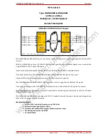
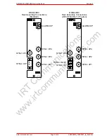
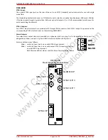
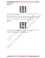
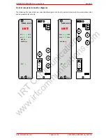
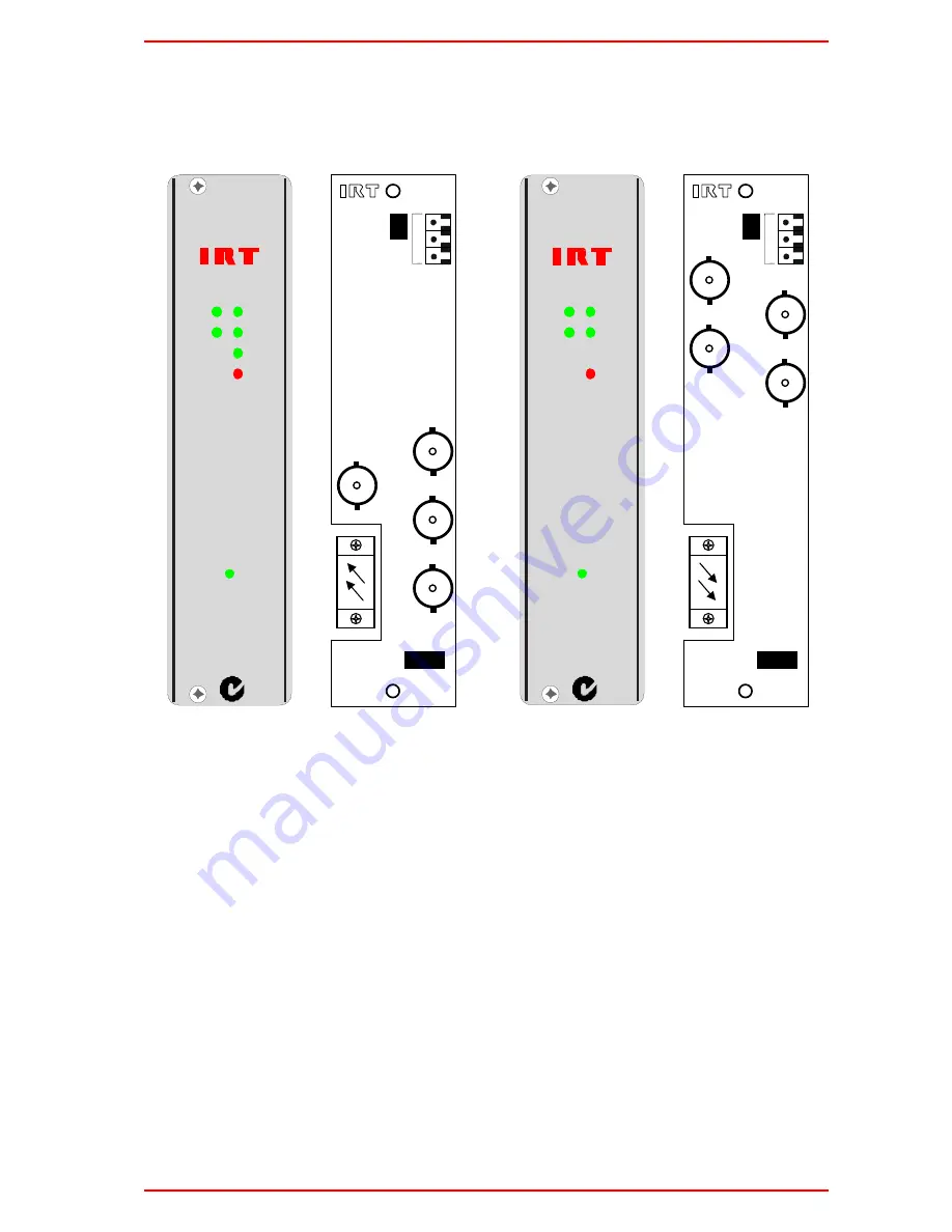
Front & rear panel connector diagrams
The following front panel and rear assembly drawings are not to scale and are intended to show connection order
and approximate layout only.
I/P 1
I/P 2
I/P 4
I/P 3
ALARM
REF I/P
DC
D MM -488 0
N140
O/P 1
O/P 2
O/P 4
O/P 3
ALARM
DC
D MX -488 0
N140
SK 9 OUT3
PL4
SK10
SK 4 OUT4
SK 8 OUT1
SK3 OUT2
PL3
1
2
3
1-GND
2-MINOR
3–MAJOR
SK 7 IN4
PL4
SK10
SK 2 IN3
PL3
SK 11 IN2
SK 6 IN1
1
2
3
1-GND
2-MINOR
3–MAJOR
IRT
Communications
www.irtcommunications.com


