8
SEC
T
IO
N
iPecs™
LAB
/ User Manual
01
02
03
04
05
06
07
08
09
10
System Overview
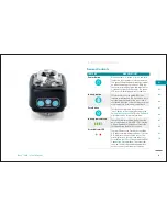
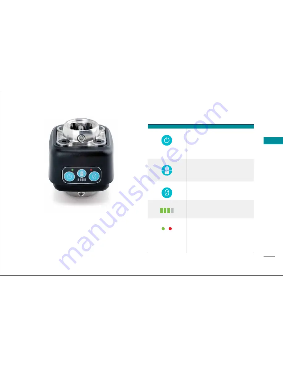
Sensor Controls
FEATURE
DESCRIPTION
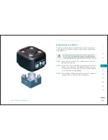
Power Button
When the sensor is turned off, press and hold
this button for 2 seconds to turn the sensor on.
The green LED above the power button remains
on indicating a power-on condition. With the
sensor on, press and hold the power button for
2 seconds to switch off the sensor. The green
LED turns off indicating power-off condition.
Battery Button
This button turns on the amber LEDs that
indicate current battery life. It also has a cross-
hair depicting the center of the sensor and is
considered the origin of the co-ordinate system
used to measure forces and moments data.
Zero Button
This button has the same function as the
“Zero” button in the software. Reference the
Pairing the Sensor and DCM
in the
M
Software
Overview
section for more information.
w
Battery Indicator LED
These LEDs indicate the remaining life of the
built-in battery pack. More ‘ON’ LEDs indicate
a longer time before the batteries have to be
recharged (using the Mini-B connector).
Error Indicator LED
The red LED above the Zero button should be
OFF under normal working conditions. If it turns
ON, it indicates an error on the sensor. The
error displays as a text message under
Last
Error
fi eld in the
r
iPecs Status
area in the DCM
s
Connection Status
window. The researcher
s
can view this message and take appropriate
action to correct/clear the error condition.
Summary of Contents for 104441-01
Page 1: ...User Manual...
Page 4: ...System Overview 01...
Page 11: ...Software Installation 02...
Page 16: ...USB Driver Installation 03...
Page 20: ...Hardware Installation 04...
Page 25: ...Software Overview 05...
Page 31: ...Recording Data 06...
Page 34: ...Uninstalling Software 07...
Page 37: ...Uninstalling USB Driver 08...
Page 40: ...System Calibration 09...
Page 46: ...Troubleshooting 10...


