43
SEC
T
IO
N
iPecs™
LAB
/ User Manual
01
02
03
04
05
06
07
08
09
10
STEP 2
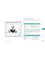
Connect the USB cable connection between the DCM
and PC that will run the iPecs Lab software.
STEP 3
Turn the sensor
ON
. It is required for this procedure.
STEP 4
Start the iPecs Lab application.
STEP 5
In the iPecs Lab software main window, click the
Connect to sensor
button on the toolbar.
r
STEP 6
Use the Command control to select
Test Pattern High
from the drop-down menu. Click the
Command
control
d
button
Send
to cause the test selection to be sent to
d
the DCM. The DCM output voltage should be set to
approximately
negative 2.4 volts
.
STEP 7
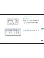
Record the voltage measured by the data acquisition
system for 8 data channels in the calibration calculation
workbook
xxxxxx Analog Interface Calibration.xls
,
that was included in the install CD.
Summary of Contents for 104441-01
Page 1: ...User Manual...
Page 4: ...System Overview 01...
Page 11: ...Software Installation 02...
Page 16: ...USB Driver Installation 03...
Page 20: ...Hardware Installation 04...
Page 25: ...Software Overview 05...
Page 31: ...Recording Data 06...
Page 34: ...Uninstalling Software 07...
Page 37: ...Uninstalling USB Driver 08...
Page 40: ...System Calibration 09...
Page 46: ...Troubleshooting 10...


