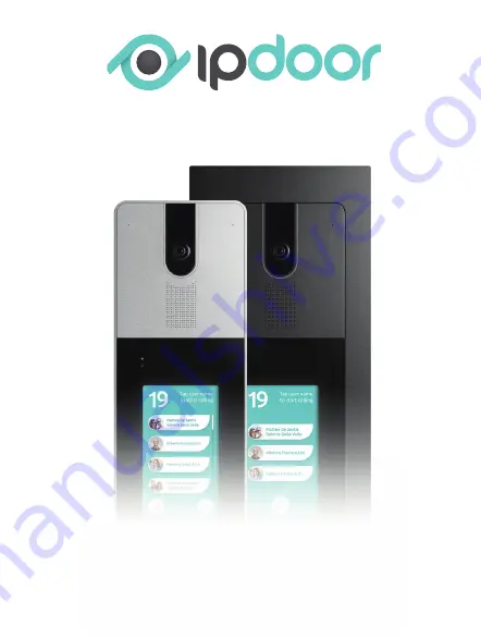
Wall
Quick
Start
Guida Rapida
A New Interactive Experience
Manufactured by InfinitePlay S.r.l.
Via Giacinto Andrea Longhin, 131 - 35129 Padova (PD) Italy
03 | 2020
Per registrare la targa in una ret
e wireless, premere a lungo nella parte
alta dello schermo, accedere alle impostazioni di rete, selezionare la
propria rete tra quelle disponibili ed inserire i dati di accesso.
To register the door statio
n in a wirel
ess network, long press at the top of
the screen, access the network settings, sel
ect your network from those
availabl
e and enter the access data.
Utilizzare un alimentatore stabilizzat
o 24V @0.5A tipo ICA0001.
Facendo riferiment
o all’uscita 24V dell’alimentatore, c
ollegare il
positivo all’ingresso 24V @0,5A ed il negativ
o all’ingresso M sui
morsetti della targa.
Use a 24V @0.5A sta
bilized power
supply lik
e ICA0001. R
eferring to
the 24V output of the power supply, c
onnect the positive to the 24V
@0.5A input and the negative to the M input on the door station clamps.
I morsetti AUX1 identificano un
’uscita relè (NA) con caric
o massimo
supportato di 1A
@24V o 1A@24V .
The AUX1
terminals identif
y a relay output (NO) with a ma
ximum suppor-
ted load of 1A@24V or 1A@24V .
Configur
azione WI-FI
WI-FI Configur
ation
Collegament
o Ingressi All
arme
Connec
tion of Alarm Input
s
Collegament
o Alimentat
ore Est
erno
External Power Supply C
onnection
Collegament
o Uscita R
elè
Rel
ay Output Connec
tion
Morsetti e Connett
ori
Terminals and C
onnectors
IP120D
IP220D
Collegament
o Elettroserr
atura
Elec
tric Lock C
onnection
90°
-90°
0°
180°
45°
315°
270°
90°
225°
135°
24V @ 0,5A
RS485 -
IN1
AUX1
Lock+
M
RS485 +
IN2
AUX1
Lock
-
Vista dall’alto
Top View
Area a bassa c
opertura
Low c
over
age area
Area ad al
ta c
opertura
High cover
age area
B
L ’installazione
wireless si
realizza connett
endo la
scheda Wi-fi
a 2.4Ghz
integrata
ad un
access point
o rout
er wireless.
Questo
tipo di
collega
-
mento
prevede
l’utilizzo
di un
alimentatore
esterno
24V
tipo
ICA0001
da collegare direttament
e alla targa.
The wireless install
ation is made connec
ting
the integr
ated 2.4Ghz
Wi-fi car
d
to a wireless ac
cess point or router
. This type of connec
tion requires the use
of an external 24V power supply lik
e ICA0001 to be c
onnected direc
tly to
the door station.
L ’installazione
LAN
si realizza
collegando
un ca
vo
di ret
e C
AT5/6
tra la
scheda di
rete,
posta sul
retro della
targa, ed
il rout
er (o
uno swit
ch).
Questo
tipo di
collegament
o prev
ede l’utilizz
o di
un alimentat
ore est
er
-
no 24V tipo ICA0001 da c
ollegare direttamente alla targa.
The LAN install
ation is made c
onnecting a C
AT5/6 network c
able between
the network car
d, loc
ated on the back of the door station, and the router (or
switch). This type of c
onnection requires the use of an external 24V power
supply lik
e ICA0001 to be c
onnected direc
tly to the door station.
L ’installazione
PoE
si realizza
collegando
un ca
vo
di ret
e C
AT5/6
tra la
scheda di
rete,
posta sul
retro della
targa ed
un Inject
or tipo
ICA0002
od
uno swit
ch PoE
IEEE802.3af. In
questa modalità
l’alimentazione è
fornita
direttamente
attraverso
il ca
vo
di ret
e pertant
o non
è necessario
utiliz
-
zare un alimentatore est
erno.
The PoE install
ation is made c
onnecting a C
AT5/6 network c
able between
the network car
d, loc
ated on the back of the door station and an injector lik
e
the ICA0002 or an IEEE802.3af PoE switc
h. In this case the power is supplied
directl
y through the network cabl
e, therefore it is not nec
essary to use an
external power supply.
Schema con c
ollegamento di ret
e wireless ed alimentatore est
erno
Diagram with wirel
ess network connec
tion and external power supply
Schema di collegament
o con ca
vo di ret
e CA
T5/6 ed alimentatore est
erno
Connec
tion diagram with C
AT5/6 network c
able and
external power suppl
y
Schema di collegament
o con ca
vo di ret
e CA
T5/6 ad un dispositivo P
oE
IEEE802.3af senza alimentatore est
erno
Connec
tion diagr
am with CAT5/6 network c
able to a PoE IEEE802.3af devic
e
without external power supply
Install
azione WI-FI
WI-FI Installation
Install
azione LAN
LAN Install
ation
Install
azione PoE
PoE Installation
Vista Frontale
Front View
M
Ingresso generico
Generic input
Pulsante est
erno apriporta
External door button
IN2
IN1
L
CAT
5/6
PSU 24V
Door Station
Internal
Units
Smartphone
WI-FI
WI-FI
Router
Cloud
Gli ingressi “IN1” e “IN2” vanno riferiti alla massa “M”.
Per aggiungere un pulsant
e apriporta esterno, c
ollegare il pulsante
tra i morsetti IN1 (o IN2) e M ed associare l’ingresso scelto all’azione
uscita OUTPUT nelle impostazioni della targa.
The inputs “IN1” and “IN2” must refer
to ground “M”.
To add an external door opener button, c
onnect the button between termi
-
nals IN1 (or IN2) and M and associate the c
hosen input with the OUTPUT
output action in the door station settings.
Max 50m - sez. min. 1,5mm
12V @1A
LOCK+
LOCK
-
L
Per c
onfigurare il dispositivo e c
onsultare la documenta
-
zione completa accedi alla
console di amministr
azione.
To c
onfigure the device and c
o
nsult the compl
ete documen-
tation, access the
administration c
onsole
.
https://consol
e.ipdoor.c
om/
Flush
Touch
130mm
95mm
20mm
2mm
25mm
42mm
262mm
311mm
ww
w.ipdoor
.com
IT/EN
2
0
m
1
0
m
1
5
m
1
0
m
85
~
264 V
24V
24V @0,5A
M
INPUT
OUTPUT
L
ICA0001
N
L
v+
+
v-
-
N
L
Alimentat
ore
Powe
r Suppl
y
L
AUX1
220
V
AUX1
AUX1
AUX1
Max 24V @1A
Max 24V @1A
o
Alimentat
ore
Powe
r Suppl
y
Schema di
collegament
o dirett
o
Direct c
onnection diagr
am
Schema di collegament
o tramite relè di pot
enza
Connec
tion diagram via power rel
ay
Max 24V @1A
Max 24V @1A
o
OIO
GIB
BIG
BrlBr
Rj-45 Plug
RJ-45 EIA
/TIA 568B
CA
T5/6
Presa di rete/
Network Socket
Scheda rete/
Network Car
d
:
10/100Mbps PoE IEEE 802.3af
.
A
Per
ottenere
prestazioni migliori
posizionare la
targa nell’area
ad alta
copertura.
For best perf
ormance, pl
ace the door station in the high c
over
age area.
CAT
5/6
max 100m
PSU 24V
Door Station
Internal
Units
Smartphone
WI-FI
Router
Cloud
CAT
5/6
C
AT
5/6
max 100m
Injector
or PoE
switch
Door Station
Internal
Units
Smartphone
WI-FI
Router
Cloud
CA
T
5/6
max 100m
CAT
5/6
Scaric
abile su /
Avail
able on
2
51mm
Made in ital
y
A
Porta E
thernet
Ethernet port
B
Morsetto estraibile a 10 poli
Remo
vable 10-pol
e terminal
C
Ripristino impostazioni di
fabbrica
Premere per 10 secondi al ria
vvio
Fac
tory reset
Hold f
or 10 seconds on reboot
51mm
La targa dispone di un’uscita alimentata
12V 1A
per l’azionamento
di una serratura elettrica senza l’ausilio di un alimentatore
supplementare. La serratura va connessa, seguendo lo schema del
produttore, ai morsetti “
LOCK+
” e “
LOCK
-
” rispettivamente positiv
o
(
+12V
) e negativo (massa
) con un ca
vo elettric
o di
lunghezza massi
-
ma
50 metri
e
sezione minima 1,5mm.
The door station ha
s a 12V 1A powered output for the drive of an
elec
tric lock without the aid of an additional power suppl
y. The l
ocks must
be connec
ted, foll
owing the manufacturer
’s scheme, to the terminals
“LOCK +” and “L
OCK-” respec
tively positive (+ 12V ) and negative (
earth)
with an elec
tric cabl
e with a maximum l
ength of 50 meters and minimum
section 1,5mm.
2
2
Summary of Contents for IP120D
Page 1: ...Quick Start Guida Rapida A New Interactive Experience ...
Page 24: ......


