21
SERVICE
ALARM
CAUSE
SOLUTION
PF1/PFH
DEFAULT SENSOR “SP1”
DEFAULT SENSOR “SPH” (RH)
Turn off and restart the cabinet, if
the problem persists, contact service
center
PF2/PFT
DEFAULT SENSOR “SP2” “SPT” See above
PF3
DEFAULT SENSOR “SP3”
See above
EER
PCB ERROR
See above
DEFAULT DIAGRAM
In most cases, operational difficulties are related to banal causes or to erred electrical in-
stallation.
These causes can therefore be easily remedied on-site by an electrician or, sometimes, with-
out even having to contact a technician.
If after these checks operations are still not corrected, contact your distributor to request
technical assistance.
PROBLEM
POSSIBLE CAUSE AND SOLUTION
LIGHT (13) AND DISPLAY
DOES NOT TURN ON
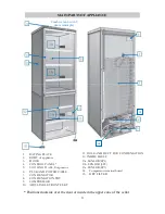
VERIFY SWITCH (I)(1) ON/OFF ACTIVED
VERIFY POWER POINT
VERIFY INSERT PLUG CORRECT
VERIFY COMPRESSOR TERMINAL BOARD
(Unplug the unit and press with care T.B. toward compressor)
UNIT DON’T REACH SET POINT
TEMPERATURE
VERIFY DOOR CLOSING
VERIFY DOOR GASKET (DAMAGE, DIRTY OR INCORRECT POSI-
TION)
VERIFY AERATION OR PROXIMITY HEAT SOURCE
CONDENSER AND REAR SIDE TOO NEAR TO THE WALL OR DIR-
TY
VERIFY SET POINT TEMP. WITHIN LIMITS INDICATED
VERIFY UNIT VERSION: MONO, MULTI OR DUAL TEMP.
ICE ACCUMULATION
VERIFY DOOR CLOSING
VEIRY DOOR GASKET(DAMAGE OR INCORRECT POSITION)
MAKE MANUAL DEFROSTING, IF THE PROBLEM RETUERN
PLEASE CONTACT SERVICE
NOISE PROBLEM
VERIFY APPLIANCE LEVELLING
MOVE THE APPLIANCE TO THE REAR WALL AT LEAST cm 5
VERIFY POSITION OF COMPRESSOR EVAP.TRAY
INNER LIGHT DON’T RUN
VERIFY SWITCH(2) ACTIVATED
IMPORTANT: BEFORE REMOVING POWER TO THE EQUIPMENT, PRESS
THE START-UP BUTTON (1) IN THE OFF POSITION. IF THIS OPERATION
IS NOT PERFORMED, WHEN POWER IS RESET, AN "ERROR" OR "EEP"
ALARM COULD APPEAR ON THE DISPLAY. TO DEACTIVATE THE
ALARM, RESTART THE EQUIPMENT WITH THE START-UP BUTTON (1).

