background image

10


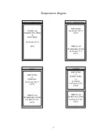
To know the temperature of  the upper zone, keep pushed button 3 ▲ 


The small point in this position means that we are reading the programmed  
temperature of  the upper zone.


TEMPERATURE ADJUSTMENT OF COMBIWINE® 


Combiwine

®

 models (601/402) are equipped with 2 compressors: one for lower cellar 

(right compressor seeing from behind) and one for upper cellar (left compressor). It’s 
suggested to use lower cellar for white and sparkling wine (6°C), upper cellar for red wine 
(18°C) or storage (12/14°C)


•  Visualization and modification of  programmed temperatures


Push 

SET

 for 5 seconds until the word 

SP1

 appears (it means that you are under setting operation of 

temperatures). 
Push 

SET

 again and the programmed temperature of  lower cellar  will be visualized 

Modify programmed temperature by 2 and 3 (▲▼) and push 

SET

 again to confirm. 

To regulate the temperature of upper cellar keep pushed 

SET

 until the word 

SP1

 appears.  

By pushing ▲ the word 

SP2

 will appears and then, by pushing 

SET

 again, the programmed temper-

ature of upper cellar  will be visualized. 
Modify programmed temperature by ▲▼ and push 

SET

 to confirm. 

Please note

 that the number visualized on the display indicates the temperature of lower cellar  

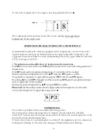
To know the temperature of upper cellar  keep pushed  ▲ 

Dis. 2


1


8


S


P


2


DEFROSTING  

Your cellar is provided with an automatic defrosting system.  
The refrigeration will be interrupted for 15 minutes: the pilot light (10) will flash. 
Once the 15 minute interval has passed, the cellar will resume its normal operation at the 
previously programmed temperatures.    
At least once a year, it is recommended to switch off  the appliance and do a manual de-
frosting and cleaning of  the cellar. (See also pag. 20 Maintenance and cleaning)                                             

Summary of Contents for CEXK 2503

Page 1: ...1 WINE CELLARS USER INSTRUCTIONS MANUAL Rev 00 del 01 04 18...

Page 2: ...2 PAGE INDEX...

Page 3: ...3 SAFETY WARNINGS...

Page 4: ...4 EN 60335 1 EN 60335 2 EN 55014 1 EN 55014 2 EN 61000 3 2 EN 61000 3 3 EN 62233 2008 GENERAL INFORMATIONS SAFETY WARNINGS...

Page 5: ...tions are NORMAL quantified in 200 LUX E D 2006 42 EEC Ambient temperature it mean temperature immediate proximity of the cabinet TECHNICAL INFORMATION Class Symbol Ambient temperature range C Extende...

Page 6: ...e connected and does not start immediately this is to be considered completely normal After a short period of time equipment operation will automatically start again SUPPORT FEET ADJUSTMENT Arrange th...

Page 7: ...p to the base to avoid damage Tape the door shut Be sure the appliance stays secure in the upright position during transportation Also protect outside of appliance with a blanket or similar item For t...

Page 8: ...pper cellar 8 RED LED Heating operation In Combiwine and Dual down cellar 9 RED LED Heating operation only for Combiwine and Dual upper cellar 10 PROBE 1 OPERATION INDICATOR LIGHT MANUAL DEFROST INDIC...

Page 9: ...performance the following temperature settings are suggested for multi temperature cellars Bottom part SP1 from 5 C to 7 C for dual 5 C 10 C For sliding door 6 10 C Top part SP2 from 15 C to 18 C for...

Page 10: ...lized Modifyprogrammedtemperature by 2and3 andpushSETagain toconfirm Toregulate the temperatureof uppercellar keeppushedSETuntil thewordSP1appears Bypushing theword SP2willappearsandthen bypushingSETa...

Page 11: ...8 C SP1 MULTI TEMPERATURA RED WINE Set Point 15 18 C SP2 WHITE and SPARKLING WINE Set Point 5 7 C SP1 RED WINE or STORAGE Set Point 10 18 C SP2 WHITE and SPARKLING WINE Set Point 5 10 C SP1 COMBI RED...

Page 12: ...llar mobile is inserted and properly fastened in the compartment it is essential to also fix the appropriate grid aeration supplied to the base of the kitchen or modular furniture Ventilation min 200...

Page 13: ...13 BUILT IN VERSION MODEL CI 301 401 501 601 2501 SD Maximum dimensions allowed For built in installation...

Page 14: ...side Secure the lock plates of the door panel into the opposite side Secure the door to the hinges CI 140 IX Model with stainless steel door C 141 Model with glass door To change which way the door i...

Page 15: ...RATURE 12 STAND BY INDICATOR LIGHT with display OFF Version 601 2 doors control panel of top cellar is located inside the cellar Pic 1 The control panel of the bottom cellar generally the one with the...

Page 16: ...y pushing 3 it will appear the word SPT If you push SET again the programmed temperature will be visualized To modify the programmed temperature you have to push 2 3 and push SET again to confirm a b...

Page 17: ...gent to refill water Remove upper housing fill water into the lower housing 2 litres of water no more Device may neverbe filled with upper part in place A ASSEMBLE AND DISSASSEMBLE DEVICE For opening...

Page 18: ...elf back Sliding shelf 3 4 Remove the shelf remove the metal rails interlocking on plastic rails remove plastic rails by unscrewing the two screws insert the rails at the desidered level screw in put...

Page 19: ...nd HALF SHELF FOR SUPPORT BOTTLES 45 MAXIMUM CAPACITY 6 BOTT DA 750 ML KG 10 SHELVES REACH Indicate below the maximum capacities of the different types of shelves for your safety we recommend that you...

Page 20: ...c parts Wash with warm water and mild detergent It is important to keep the door gasket clean suggest specify product for car dashboard to prevent any odours inside the wine cellar Wooden cellar outsi...

Page 21: ...RESSOR TERMINAL BOARD Unplug the unit and press with care T B toward compressor UNIT DON T REACH SET POINT TEMPERATURE VERIFY DOOR CLOSING VERIFY DOOR GASKET DAMAGE DIRTY OR INCORRECT POSI TION VERIFY...

Page 22: ...___________________________________________________________________ ________________________________________________________________________________________________ ___________________________________...

Page 23: ...WALL Evaporator 6 PLUG AND POWER CABLE 7 CONDENSATOR 8 CONDENSATION TRY 9 COMPRESSOR 10 ADJUSTABLE FRONT FEET 11 HOLE AND DUCT FOR CONDENSATION 12 INSIDE SHELF 13a SENSOR SP1 13b SENSOR SP2 13c SENSO...

Page 24: ...please contact Certified Quality System ISO 9001 2008 IP INDUSTRIE SPA Strada Nuova 16 43058 Coenzo di Sorbolo Parma Italy Free phone number 800 488 009 Office Phone 39 0 521 699232 Fax 39 0 521 6995...

Reviews: