90
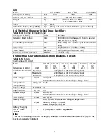
8.6 Electrical Characteristics (Inverter Output)
Table 8-6:
Inverter output (to critical load)
Rated power (kVA)
Unit 30 ~ 300
Rated AC voltage
1
Vac
380/400/415 (three-phase four-wire, with neutral
reference to the bypass neutral)
Frequency
Hz
50/60 Auto Selectable
Overload
%
105%~110% for 60min
110%~125% for 10min
126%~150% for 1min
>150% for 200ms
Neutral current capability
%
170%
Steady state voltage stability %
± 1 (balanced load), ± 2 (100% unbalanced load)
Total harmonic voltage
%
<2 (linear load), <4 (non-linear load3)
Synchronization window
+/- 1Hz, +/- 2Hz, +/- 4Hz (default: 4Hz)
Note:
1. Factory setting is 400V. 380 or 415V is selectable by commissioning engineer.
8.7 Electrical Characteristics (Bypass Mains Input)
Table 8-7
: Bypass mains input
Rated power (kVA)
Unit 30 ~ 300
Rated AC voltage1
Vac 380/400/415 (Three-phase four-wire, sharing neutral with
the rectifier input and providing neutral reference to the
output)
Rated current
A
30U for 90KW
171, 380V / 164, 400V / 157, 415V
42U for 120KW
228, 380V / 218, 400V / 209, 415V
42U for 210KW
397, 380V / 380, 365V / 329, 415V
42U for 300KW
570, 380V / 546, 365V /532, 415V
Overload
%
105%~110% for 60min
110%~125% for 10min
126%~150% for 1min
>150% for 200ms
Upstream protection, bypass
line
N/A Circuit breaker, rated up to 100% of nominal output
current.
Current rating of neutral cable A
1.7 × In
Frequency
Hz
50/60 Auto Selectable
Transfer time (between bypass
and inverter)
ms
Synchronous transfer: ≤20ms
Bypass voltage tolerance
%Va c Upper limit: +10, +15 or +20, default: +15
Lower limit: -10, -20, -30 default: -20
(delay time to accept steady bypass voltage: 10s)
Frequency Range
Hz
+/- 1Hz, +/- 2Hz, +/- 4Hz (default: 4Hz)
Note
:
1. Factory setting is 400V. 380V or 415V is selectable by commissioning engineer.


