background image


-

 7 -


1.2.1


Front Panel Controls and Indicators 

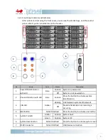
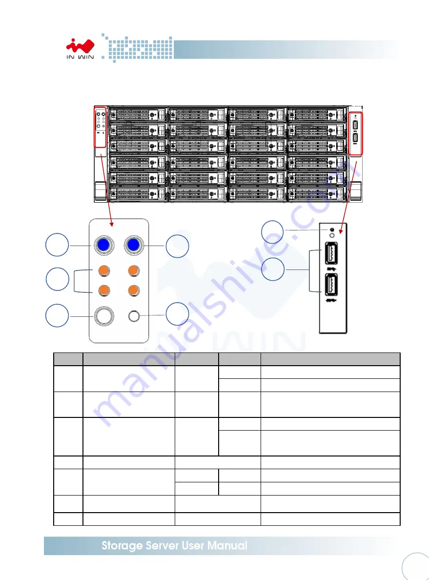
After unlock and removing the front cover, you can see the 24 disk bays, and the control 

panel, USB IO ports and indicators on the handles.   


No. 

Name 

Color 

Status 

Description 

Power ON/OFF Button 

with LED 

Blue 

Solid on  System is powered on 

Off 

System is not powered on 

Chassis ID Button with LED 

Blue 

Solid on 

Press the button to activate system 

identification 

LAN LED 

Amber 

Blinking  Link between system and network 

Off 

No date transmission or receiving is 

occurring 

NMI Button 

NO LED defined 

Press the button to activate user define 

System Fail LED 

Amber 

Solid on  System Fault 

Green 

Solid on  System OK 

System Reset Button 

NO LED defined 

Press the button to activate system reset 

USB3 Connector 

NO LED defined 

USB devices connection 


Summary of Contents for IW-RS104-02M

Page 1: ...IW RS424 02M User s Manual...

Page 2: ...Fan Module P 11 2 3 1 Removing a Fan Module P 11 2 3 2 Installing a Fan Module P 11 2 4 Removing and Installing a PSU Module P 12 2 4 1 Removing a PSU Module P 12 2 4 2 Installing a PSU Module P 13 2...

Page 3: ...m is designed to operate in a typical office environment The location should be a clean dry and free of airborne particles a well ventilated room and away from sources of heat including direct sunligh...

Page 4: ...is a short length of conductor used to close open or bypass part of an electronic circuit Jumpers on In Win backplane have a small tab on top that you can pick up with your fingertips Grip the jumper...

Page 5: ...2U 1 1 Redundant Watt Redundant up to 875W Indicator Power LED LAN1 LAN2 LAN3 LAN4 LED System LED ID LED Front Control Panel Power Switch ID Switch System Reset NMI USB 3 0 x 2 Backplane Mini SAS 6Gb...

Page 6: ...5 1 Product Introduction 1 1 Box Content When you open the carton box of IW RS424 02M the contents should include...

Page 7: ...open the top cover should be like the diagram shows Top cover CRPS Redundant or Single module power supply 24 x 3 5 tool less HDD slots 120 x 38 mm PWM Easy Swap Fan x 3 mm PWM Rear Fan x 2 ATX or EE...

Page 8: ...owered on 2 Chassis ID Button with LED Blue Solid on Press the button to activate system identification 3 LAN LED Amber Blinking Link between system and network Off No date transmission or receiving i...

Page 9: ...s cover and replace as redundant PSU housing case bracket 2 Power Supply Window This window is for installing single PSU please reference In Win compatibility list to select the compatible models 3 Sy...

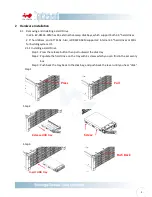
Page 10: ...ternal 2 5 hard drives or SSDs for building system OS 2 1 1 Installing a Hard Drive Step 1 Press the release button then pull outward the disk tray Step 2 Populate the hard drive on the tray with 4 sc...

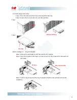
Page 11: ...1 3 Installing 2 5 2bay SSD module Step 1 Remove the slot bracket to left the space for the module Step 2 Place the module to the chassis and use screw to fix the module form side wall and slot frame...

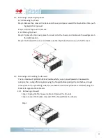
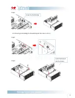
Page 12: ...e cover and make sure the clip clicks then screw up to fix the cover 2 3 Removing and Installing the fan wall The fan module of IW RS424 02M is flexible which you can move forward or backward to optim...

Page 13: ...12 Step 2 2 3 2 Moving and installing the fan wall Repeat the actions of 2 3 1 Step 1 Step 2 Loose the thumb screw Install the fan wall into the chassis...

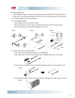
Page 14: ...models 2 4 1 Installing Redundant PSU Step 1 Unscrew and remove the rear frame at the rear right position of the chassis Step 2 Measure the length of the PSU housing case and post the rear bracket to...

Page 15: ...ount the inner rails onto the chassis by the direction which the arrows show Step 3 Install the outer rails and the brackets onto the rack Step 1 Step 2 Step 3 2 5 3 Mount the chassis onto the cabinet...

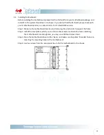
Page 16: ...vice Step 1 Measure the motherboard location and removing the plastic dots to appear the holes Step 2 Install the steel pillars which you can find in the accessories box to the holes matching the moth...

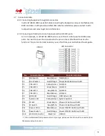
Page 17: ...find from your motherboard s user guide If the motherboard s led power source is 3 pin type please use the 2Pin to 3Pin convertor form the accessory box to connect No Connector Name Color Front IO In...

Page 18: ...plane is different by order Please reference the backplane user guide to complete the installation Visit In Win website https www in win com en ipc server The download link is at the download section...

Page 19: ...ODM service user can contact In Win sales for customization c Does the chassis support 3 5 2 5 SAS and SATA drive Can I mix the different type of drives in an enclosure A In Win IW RSXXX 02M supports...

Page 20: ...uld like to mount a customized motherboard which not meet Intel s standard you will need to contact In Win partners or sales for customization service h Do I need a RAID controller card to connect the...

Reviews: