


15
Seat Width Adjustment
Whilst the seating width and depth adjustments, will be factory set to the specifications
requested on the prescription form, there may be times where these need to be altered to
accommodate changes in the User’s growth, or their disability.
It will be necessary however, following the adjustments, to replace the Seat Board, Cushion and
Backrest, with the correct size to suit the new Seat width.
IMPORTANT NOTE:
Where a 14" seat width is to be increased to 16" on a Powered Tilt model,
it will also be necessary to install the longer16" model rear Seat Locators and Front Seat Lock
Assembly, see below. (Please call RMS Sales for part numbers and prices).
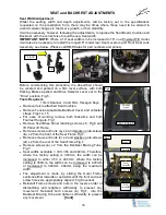
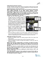
Before commencing this procedure, the wheelchair should
be vacated and parked on a firm level surface, with both
Parking Brakes applied and Drive Selector Lever set to the
“Drive” position, Fig.5.
Tools Required:-
13mm Spanner, 4 and 6mm Hexagon Keys.
Remove Velcro attached Seat Cushion.
Remove Tension Adjustable Backrest Cover and unfasten
straps. Figs.12 -15.
For ease of working, remove both Sidearms and both
Footrest Hangers. Fig.1
Remove Seat Base Panel retaining screws x 6, Fig.6 and
lift Panel off Frame.
Remove screws and nuts (
a
) x 2 and slacken grub-screws
(
b
) x 2 from the front of the Seat Frame Fig.7.
Remove screws and nuts (
c
) x 2 and slacken grub-screws
(
d
) x 2 from the rear of the Seat Frame Fig.7.
Remove screws (
e
) x 2 from the Backrest Bracing Tube.
Fig.7.
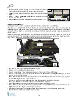
Seat widths available = 300, 350 and 400mm. Therefore,
where the factory setting is 300mm, the width can be
increased to either 350 or 400mm. Where the factory
setting is 350mm, the width can be increased to 400mm
or decreased to 300mm. 400mm being the maximum
width.
The adjustment is made, by sliding the Outer Frame
sections either inwards or outwards until the front and rear
screw holes are appropriately aligned, Fig.8 overleaf.
Reinstall Frame screws and nuts in the reverse order of
dismantling and retighten sufficiently to prevent any
movement. Reinstall both screws (
e
) Fig.7, into the
Backrest Bracing Tube and tighten sufficiently to prevent
any movement.
[Cont]
SEAT and BACKREST ADJUSTMENTS
Retaining
Screws
Grub-
screws
d
Screws
a
Screws
c
Grub-
screws
b
Screws
e
Fig.6
Fig.7
SEAT BOARD
12 & 14"
16"
Summary of Contents for IPC-S
Page 1: ...Powered Wheelchairs Instructions for Use Models IPC S and IPC T Edition Two Feb 2013...
Page 2: ...2...
Page 41: ...41 USER NOTES...
Page 42: ...USER NOTES...
Page 43: ...USER NOTES...


