


Easy Start Guide
Page 10
This guide has been produced by The Inverter Drive Supermarket Ltd.
All content, including but not limited to graphics, text and procedures copyright
The Inverter
Drive Supermarket and must not be reproduced or altered without prior written permission.
©
10. How to connect and configure a Potentiometer
for remote speed control
Parameter
Description
How to set
P000
Parameter Access
Set to
to allow parameters to be changed
5
P221
Frequency Local Reference
Set to
to use the keypad up/down keys or 1 to enable the Potentiometer in Local mode
0
P222
Frequency Remote Reference
Set to
to enable the Potentiometer via AI1 in Remote mode
1
P133
Minimum Frequency
Set to
for Potentiometer lowest speed of 5Hz (or set as required)
5
P134
Maxmum Frequency
Set to
for Potentiometer highest speed of 50Hz (or set as required)
50
P233
Analog Input Dead Zone
Set to
to set 0V to min speed and 10V to max speed so full Potentiometer rotation is used
0
P235
Analog Input AI1 Function
Set to
to enable 0-10V (check S1:3 DIP switch behind keypad is off)
0
10.1 Parameters to change for remote Potentiometer speed control
If the up/down buttons on the keypad are
unsuitable for the application, a remote
Potentiometer can be used instead.
This provides the benefit of allowing motor
speed to be controlled from a more convenient
location such as a cabinet door (if the CFW-08
is cabinet-mounted) or on the machine itself.
A Potentiometer of
rating should be
used. The number of turns depends on the
application but both single turn and ten turn
Potentiometers are available from The Inverter
Drive Supermarket at InverterDrive.com.
10kOhm
Ensure the Inverter is in “Remote” mode
before continuing.
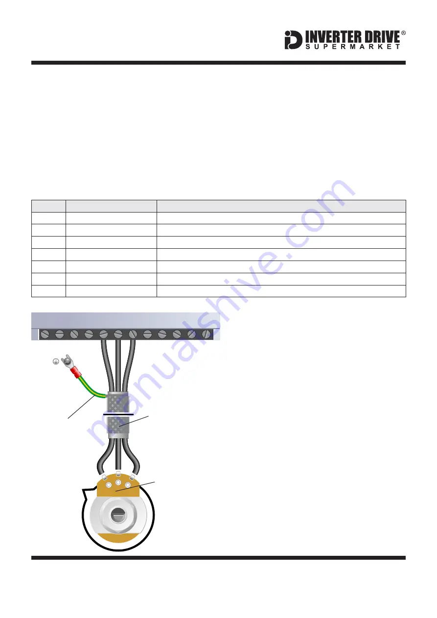
10.2 Connecting the Potentiometer
A wiring diagram is shown in the illustration
opposite. The most important connection at
the Potentiometer end is the centre terminal or
“wiper”.
The wiper will output a variable voltage
between 0 and 10 volts and should be
connected to terminal 6 at the Inverter end. It is
this voltage which provides the speed signal
with 0V being slowest and 10V fastest.
Set the Potentiometer at its “half-way” position
before running the motor for the first time. If the
rotation of the Potentiometer is the opposite to
that required (ie. turn anti-clockwise to
increase speed instead of clockwise) reverse
conne10V and COM.
Use shielded SY cable between Potentiometer
and Inverter and ensure that the cable screen
is connected to the Inverter earth terminal.
2
1
3
10kOhm
Potentiometer
[Order Code 21302]
Screened
“SY” Cable
Screen to
Earth Terminal
WEG CFW-08 Series Inverter
1 2 3 4 5 6 7 8 9 10 11 12
AI1
COM
+10V
2
3
1


