


Optidrive HVAC User Guide V2.00
38
www.invertekdrives.com
9
Ext
e
n
d
e
d
Pa
ra
m
e
ter
s
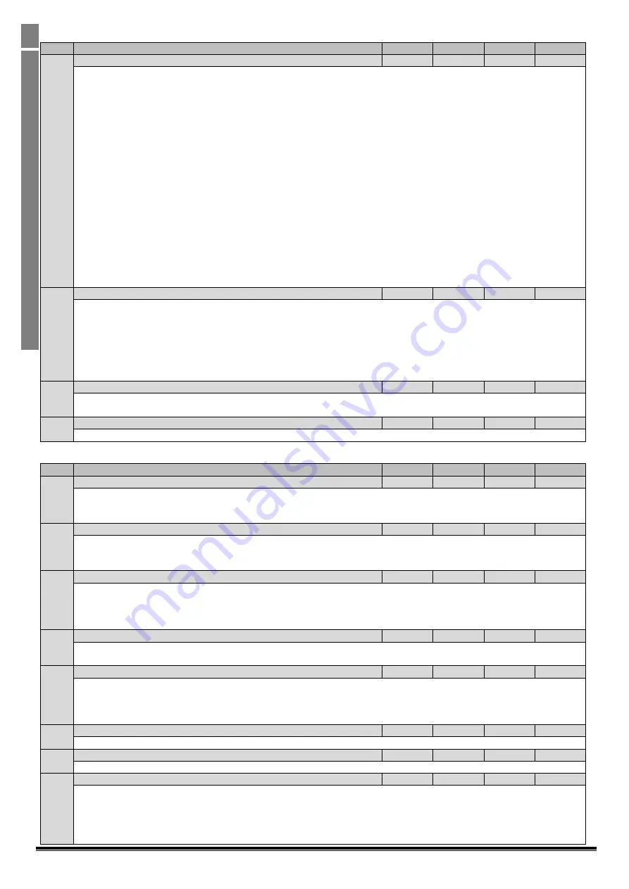
Par
Parameter Name
Minimum Maximum
Default
Units
P2-37 Keypad Restart Speed
0
7
2
-
Options 0 to 3 are only active when P1-12 = 1 or 2 (keypad Mode)
0 : Minimum Speed
. Following a stop and restart, the drive will always initially run at the minimum speed P1-02
1 : Previous Operating Speed
. Following a stop and restart, the drive will return to the last keypad set-point speed used prior to
stopping
2 : Current Running Speed
. Where the Optidrive is configured for multiple speed references (typically Hand / Auto control or
Local / Remote control), when switched to keypad mode by a digital input, the drive will continue to operate at the last operating
speed
3 : Preset Speed 4
. Following a stop and restart, the Optidrive will always initially run at Preset Speed 4 (P2-04)
Options 4 to 7 are only active in all control modes. Drive starting in these modes is controlled by the enable digital input on the
control terminals.
4 : Minimum Speed (Terminal Enable)
. Following a stop and restart, the drive will always initially run at the minimum speed P1-
02
5 : Previous Operating Speed (Terminal Enable)
. Following a stop and restart, the drive will return to the last keypad set-point
speed used prior to stopping
6 : Current Running Speed (Terminal Enable)
. Where the Optidrive is configured for multiple speed references (typically Hand /
Auto control or Local / Remote control), when switched to keypad mode by a digital input, the drive will continue to operate at
the last operating speed
7 : Preset Speed 4 (Terminal Enable)
. Following a stop and restart, the Optidrive will always initially run at Preset Speed 4 (P2-04)
P2-38 Mains Loss Stop Mode
0
2
0
-
Controls the behaviour of the drive in response to a loss of mains power supply whilst the drive is enabled.
0: Mains Loss Ride Through
. The Optidrive will attempt to continue operating by recovering energy from the load motor.
Providing that the mains loss period is short, and sufficient energy can be recovered before the drive control electronics power
off, the drive will automatically restart on return of mains power
1: Coast To Stop
. The Optidrive will immediately disable the output to the motor, allowing the load to coast or free wheel. When
using this setting with high inertia loads, the Spin Start function (P2-26) may need to be enabled
2: Fast Ramp To Stop
. The drive will ramp to stop at the rate programmed in the Fast deceleration time P2-25
P2-39 Parameter Access Lock
0
1
0
-
0 : Unlocked
. All parameters can be accessed and changed
1 : Locked
. Parameter values can be displayed, but cannot be changed
P2-40 Extended Menu Access Code
0
9999
101
-
Defines the access code which must be entered in P1-14 to access parameter groups above Group 1
9.2.
Parameter Group 3 – PID Control
Par
Parameter Name
Minimum Maximum
Default
Units
P3-01 PID Proportional Gain
0.1
30.0
1.0
-
PID Controller Proportional Gain. Instantaneous error between the feedback and the set-point in the PID controller is multiplied
by P3-01 to produce the output from the PID controller. Higher values of proportional gain produce a larger change in the drive
output frequency in response to changes in the PID set-point or feedback signals. Too high a value can cause instability
P3-02 PID Integral Time
0.0
30.0
1.0
Seconds
PID Controller Integral Time. Accumulated error in the PID control. Uses accumulated errors between set-point and feedback
signals to influence the output from the PID controller. P3-02 is the time constant for accumulating error. Larger values provide a
more damped response. Lower values result is a faster system response but may result in instability.
P3-03 PID Differential Time
0.00
1.00
0.0
Seconds
PID Differential Time Constant. The Differential time constant references the rate of change of the feedback signal over time and
works to slow the rate of change of the PID controller, particularly as it approached the set-point. Setting a shorter time will
decrease overshoot but slow down response and may lead to instability.
Note: P3-03 is set to 0 by default which disables the
differential time constant. Care must be taken when adjusting this value outside of its default value.
P3-04 PID Operating Mode
0
1
0
-
0 : Direct Operation
. Use this mode if an increase in the feedback signal should result in an decrease in the motor speed
1 : Inverse Operation
. Use this mode if an increase in the feedback signal should result in an increase in the motor speed
P3-05 PID Reference Select
0
2
0
-
Selects the source for the PID Reference / Set-point
0 : Digital Preset Set-point
. P3-06 is used
1 : Analog Input 1 Set-point
2 : Analog Input 2 Set-point
P3-06 PID Digital Reference Value
0.0
100.0
0.0
%
When P3-05 = 0, this parameter sets the preset digital reference (set-point) used for the PID Controller
P3-07 PID Output Upper Limit
P3-08
100.0
100.0
%
Limits the maximum value output from the PID controller
P3-08 PID Output Lower Limit
0.0
P3-07
0.0
%
Limits the minimum output from the PID controller


