44
,VZLUHRIFRPSUHVVRU
ZHOOFRQQHFWHG"
,VIDQZHOO
FRQQHFWHG"
5HSODFH
FRPSUHVVRU
,VRXWGRRUIDQQRUPDO"
,VWKHVWRSWLPH
RIFRPSUHVVRUPRUH
WKDQPLQ˛
)LQLVK
/RVLQJV\QFKURQLVP
XSRQVWDUWXSRI
WKHXQLW
$GMXVW
FRQQHFWLQJZLUH
/RVLQJV\QFKURQLVP
GXULQJUXQQLQJ
5HSODFHSDUWV
RIRXWGRRU
HOHFWULFER[
,VRXWGRRUIDQ
EORFNHGE\
VWXII"
5HPRYHHUURU"
5HPRYH
VWXII
5HSODFH
RXWGRRUIDQ
)LQLVK
Y
N
N
N
Y
Y
Y
N
5HSODFHSDUWV
RIRXWGRRU
HOHFWULFER[
5HPRYHHUURU"
5HSODFH
FRPSUHVVRU
Y
N
N
Y
5HOLDEOH
FRQQHFWHG"
Y
5HSODFHSDUWV
RIRXWGRRU
HOHFWULFER[
5HPRYHHUURU"
N
N
Y
Y
N
Y
N
N
Y
Y
N
Troubleshooting
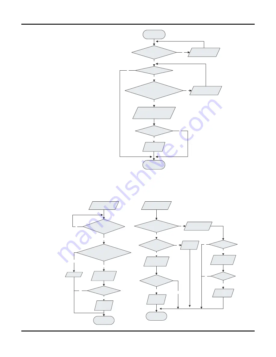
(4) Malfunction diagnosis of startup failure
Main detection points:
z
Is wiring of compressor correct
˛
z
Is the stop time of compressor enough?
z
Is compressor damaged?
Malfunction diagnosis process:
Energize the
unit and start it
Is the stop time
of compressor more
than 3min£¿
Start it 3 min later
Startup failure?
Is compressor wire connected correctly?
Connect it according
to line chart
Replace parts if outdoor
electric box
Remove the error?
Replace
compressor
finish
(5) Diagnosis of losing synchronism for compressor
Main detection points:
z
Is pressure of the system too high?
z
Is voltage too low?
Malfunction diagnosis process:
Summary of Contents for CEVI-09
Page 1: ......
Page 15: ...13 5 3 Printed Circuit Board TOP VIEW BOTTOM VIEW Schematic Diagram ...
Page 17: ...15 TOP VIEW BOTTOM VIEW Schematic Diagram ...
Page 18: ...16 FRONT VIEW BOTTOM VIEW Schematic Diagram ...
Page 19: ...17 TOP VIEW BOTTOM VIEW Schematic Diagram ...
Page 37: ...35 Outdoor Unit 1 Cooling Only Models Exploded Views and Parts list ...
Page 38: ...36 2 Cooling Heating Models Exploded Views and Parts list ...
Page 68: ...66 13 Remove Motor Sub Assy 14 Remove Fan Motor Remove Motor Sub Assy 1 Removal Procedure ...
Page 69: ......
Page 70: ......
Page 74: ......


