background image

INSTALLATION

Part No. 1145811

15

Stand Up Lift Model RPS350-2

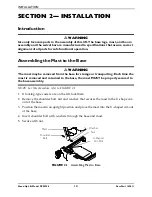
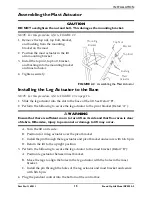
Assembling the Mast Actuator

CAUTION

DO NOT overtighten the nut and bolt. This damages the mounting bracket.

NOTE:


For


this


procedure,


refer


to


FIGURE 2.2.

1. Remove


the


top


nut,


top


bolt,


bracket,


and


bushing


from


the


mounting


bracket


on


the


mast.

2. Position


the


mast


actuator


in


the


lift


arm


mounting


bracket.

3. Install


the


top


nut,


top


bolt,


bracket,


and


bushing


into


the


mounting


bracket


and


mast


actuator.

4. Tighten


securely.

FIGURE 2.2   

Assembling the Mast Actuator

Installing the Leg Actuator to the Base

NOTE:


For


this


procedure,


refer


to


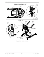
FIGURE 2.3


on


page


16.

1. Slide


the


leg


actuator


into


the


slot


in


the


base


of


the


lift.


See


Detail


“B”.

2. Perform


the


following


to


secure


the


leg


actuator


to


the


pivot


bracket


(Detail


“A”):


WARNING

Ensure that there is sufficient room to turn lift on its side and that floor area is clear 

of debris. Otherwise, injury to personnel or damage to lift may occur.

A. Turn


the


lift


on


its


side.

B. Position


slot


in


leg


actuator


over


the


pivot


bracket.


C. Install


the


pin


through


the


leg


actuator


and


pivot


bracket


and


secure


with


hitch


pin.

D. Return


the


lift


to


the


upright


position.

3. Perform


the


following


to


secure


the


leg


actuator


to


the


mast


bracket


(Detail


“B”):

A. Position


leg


actuator


between


mast


bracket.

B. Move


the


legs


to


align


the


holes


in


the


leg


actuator


with


the


holes


in


the


mast


bracket.


C. Install


the


pin


through


the


holes


of


the


leg


actuator


and


mast


bracket


and


secure


with


hitch


pin.

4. Plug


the


pendant


control


into


the


bottom


of


the


control


box.

Top Nut

Bracket

Mast 

Actuator

Bushing

Top Bolt

Mounting 

Bracket

Summary of Contents for RPS350-2

Page 1: ...l MUST be given to the user of the patient lift USER BEFORE using this patient lift read this manual and save for future reference For more information regarding Invacare products parts and services p...

Page 2: ...DEALER OR INVACARE TECHNICAL SUPPORT BEFORE ATTEMPTING TO USE THIS EQUIPMENT OTHERWISE INJURY OR DAMAGE MAY RESULT INVACARE PRODUCTS ARE SPECIFICALLY DESIGNED AND MANUFACTURED FOR USE IN CONJUNCTION W...

Page 3: ...14 Assembling the Mast Actuator 15 Installing the Leg Actuator to the Base 15 Mounting the Battery Charger 17 SECTION 3 OPERATING THE STAND UP LIFT 18 Introduction 18 Using the Pendant Buttons 18 Rais...

Page 4: ...rs 36 Replacing Forks 37 LIMITED WARRANTY 39 REGISTER YOUR PRODUCT The benefits of registering 1 Safeguard your investment 2 Ensure long term maintenance and servicing of your purchase 3 Receive updat...

Page 5: ...___________________________ 7 Would you like information sent to you about Invacare products that may be available for a particular medical condition Yes No If yes please list any condition s here and...

Page 6: ...Fold here Fold here Cut Along Line Invacare Product Registration Form Please Seal with Tape Before Mailing...

Page 7: ...ehavior PUSH the Red Power Switch OFF IMMEDIATELY DO NOT turn the Power Switch ON while transmission is in progress MAINTENANCE Maintenance MUST be performed ONLY by qualified personnel WARNING Invaca...

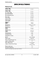
Page 8: ...rall Width 25 8 inches Caster Size FRONT REAR 3 inches 5 inches Sling Options Standing or Transport Sling Material Polyester Standing Sling Width Length 36 inches 13 inches Transport Sling Width Lengt...

Page 9: ...l site Contact your local waste management company for information Assembling the Lift DO NOT overtighten mounting hardware This will damage mounting brackets Operating the Lift Check all parts for sh...

Page 10: ...e pad or seating cushion between the patient and sling material that may cause the patient to slide out of the sling during transferring ALWAYS use the color coded strap on the standing sling closest...

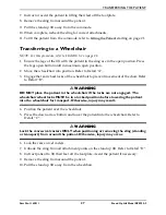
Page 11: ...slings and lifts of different manufacturers Warranty will be voided During transfer with patient suspended in a sling attached to the lift DO NOT roll caster base over objects such as carpet raised c...

Page 12: ...tric motor is sealed at the factory and if service is required the motor unit MUST be returned to the factory for repair DO NOT attempt to open the motor or obtain local service as this will VOID the...

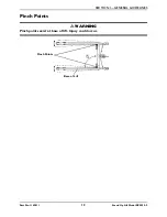
Page 13: ...SECTION 1 GENERAL GUIDELINES Part No 1145811 13 Stand Up Lift Model RPS350 2 Pinch Points WARNING Pinch points exist at base of lift Injury could occur Base of Lift Pinch Points...

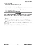
Page 14: ...se for storage or transporting Each time the mast is removed and returned to the base the mast MUST be properly secured to the base assembly NOTE For this procedure refer to FIGURE 2 1 1 If locking ty...

Page 15: ...orm the following to secure the leg actuator to the pivot bracket Detail A WARNING Ensure that there is sufficient room to turn lift on its side and that floor area is clear of debris Otherwise injury...

Page 16: ...6 Part No 1145811 FIGURE 2 3 Lift Components Base Pin Leg Mast Bracket Pin Arms Leg Actuator Mast Actuator DETAIL A SIDE VIEW OF LIFT DETAIL B Slot in Base Mast Battery Pivot Bracket Hitch Pin Hitch P...

Page 17: ...ill one mounting hole 4 Install the bottom mounting screw until there is an approximate 1 8 inch gap between the screw head and the wall 5 Install the battery charger with mounting bracket onto the bo...

Page 18: ...gs to the maximum open position If it is necessary to close the legs to maneuver the stand up lift under a bed close the legs only as long as it takes to position the stand up lift over the patient an...

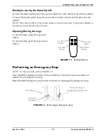
Page 19: ...lift arms will lower Opening Closing the Legs To open the legs press the legs open button To close the legs press the legs closed button FIGURE 3 1 Pendant Buttons Performing an Emergency Stop NOTE F...

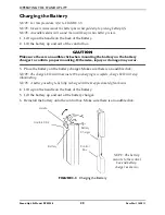
Page 20: ...charger to confirm proper mounting Otherwise injury or damage may occur 3 Place the battery on the battery charger Make sure there is an audible click NOTE The charge LED will illuminate When chargin...

Page 21: ...be in the maximum open position for optimum stability and safety If it is necessary to close the legs to maneuver the stand up lift under a bed close the legs only as long as it takes to position the...

Page 22: ...place lower the patient back onto the stationary surface and correct this problem otherwise injury or damage may occur Adjustments for safety and comfort should be made before moving the patient DO NO...

Page 23: ...um open position WARNING If transferring from a wheelchair the wheelchair wheel locks MUST be in the locked position before lowering the patient into the wheelchair Otherwise injury may occur 4 If tra...

Page 24: ...d in the lift sling roll caster base over objects such as carpet raised carpet bindings door frames or any uneven surfaces or obstacles that would create an imbalance of the lift This could cause the...

Page 25: ...r DO NOT lock the rear casters of the stand up lift when lifting an individual Locking the rear casters could cause the stand up lift to tip and endanger the patient and assistants The legs of the sta...

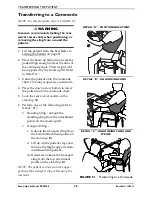
Page 26: ...sistants 4 Press the down arrow button to lower the patient onto the commode chair 5 Lock the rear swivel casters on the stand up lift 6 Perform one of the following refer to Detail B Standing Sling u...

Page 27: ...l locks of the wheelchair to prevent movement of the chair Refer to Detail B WARNING DO NOT place the patient in the wheelchair if the locks are not engaged The wheelchair wheel locks MUST be in a loc...

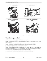
Page 28: ...osition until the down arrow button is pressed 1 Position the patient as far over the bed as possible NOTE If patient is being transferred from a surface that is lower than the bed press the up arrow...

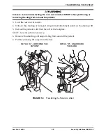
Page 29: ...swivel casters 4 Unhook the standing or transport sling from all attachment points on the stand up lift 5 Instruct the patient to lift their feet off of the footplate NOTE Assist the patient if neces...

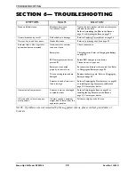
Page 30: ...ttery low RED emergency stop button pressed IN Battery not connected properly to control box The connecting terminals are damaged Actuator in need of service or load is too high Check connections Char...

Page 31: ...els of debris Inspect pivot joints for wear X X X X X X X X X X X X X X X X X X THE MAST Mast MUST be securely assembled to lift arms Inspect for bends or deflections Inspect pivot joints for wear X X...

Page 32: ...inued safety and reliability Keep lift and slings clean and in good working order Any defect should be noted and reported to your dealer as soon as possible The casters MUST swivel and roll smoothly A...

Page 33: ...ht NOTE For this procedure refer to FIGURE 7 3 1 Pick a height setting that will be comfortable to the patient and provide the necessary support NOTE The knee pad should be positioned so that the knee...

Page 34: ...ad with the mounting holes in the stand up lift 4 Using the existing hardware secure the new knee pad to the stand up lift FIGURE 7 4 Replacing the Knee Pad Replacing the Padded Cover NOTE For this pr...

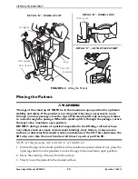
Page 35: ...lder bolt that secure the mast actuator to the mast mounting bracket 2 Rest the lift arm on your shoulder and remove the top nut bolt bracket and bushing from the lift arm mounting bracket 3 Remove th...

Page 36: ...the locknut FIGURE 7 7 Replacing Rear Casters Replacing Front Casters NOTE For this procedure refer to FIGURE 7 8 1 Place the lift on its side 2 Remove the bolt and locknut that secure the existing fr...

Page 37: ...tand up lift may occur NOTE For this procedure refer to FIGURE 7 7 and FIGURE 7 8 on page 36 1 Place the stand up lift on its side 2 Remove the front or rear caster from the lift Refer to Replacing Ca...

Page 38: ...MAINTENANCE Stand Up Lift Model RPS350 2 38 Part No 1145811 NOTES...

Page 39: ...hin 30 days of return authorization date DO NOT return products to our factory without our prior consent C O D shipments will be refused please prepay shipping charges LIMITATIONS AND EXCLUSIONS THE F...

Page 40: ...Ohio USA 44036 2125 800 333 6900 Canada 570 Matheson Blvd E Unit 8 Mississauga Ontario L4Z 4G4 Canada 800 668 5324 Invacare the Medallion Design and Yes you can are registered trademarks of Invacare C...

Reviews: