


Invacare® LiNX
Powered recline
Seat lifter
Left or center-mount powered elevating legrest
Right powered elevating legrest
Both powered elevating legrests
Powered seat tilt
Powered recline and powered elevating legrests
Stereo toggle switch
The stereo toggle switch alternates powered seating
functions of the following single power configurations:
•
Powered recline only
•
Powered seat tilt only
•
Center-mount elevating legrest (LNX) only
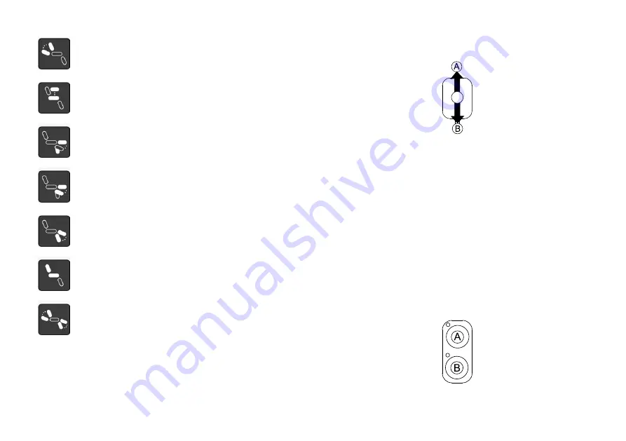
Fig. 5-84
1.
Make sure mobility device is on level surface and turned
on.
2.
Deflect and hold toggle switch up
A
or down
B
to
move particular seating function.
Seating function moves as long as toggle switch is
deflected.
Stereo button switch
The stereo button switch alternates powered seating
functions of the following single power configurations:
•
Powered recline only
•
Powered seat tilt only
•
Center-mount elevating legrest (LNX) only
Fig. 5-85
70
1637423-H
Summary of Contents for LiNX DLX-REM400
Page 124: ...Notes...
Page 125: ...Notes...
Page 126: ...Notes...
Page 127: ...www invacarelinx com...