background image


SEPAMAT F-SC_Manual_Vers.1.0e_en 


31 


Appendix 1.2   Bluetooth function in Duplex and Triplex applications 


1.  Each SMT-F-SC unit is factory initialized, allowing pre-set operation procedures to occur. Is it 

still necessary to perform a self-initialization (i.e. after a RESET), after which every device will 
be initialized individually (see note below). 

2.   In order to initiate a Bluetooth connection, the mains plug of all SMT-F-SCs must be inserted 

within 10 seconds of each other (all LEDs must be extinguished beforehand). 
All  Power  LEDs  flash  simultaneously  when  the  connection  with  the  units  is  obtained.  This 
procedure lasts for approx. 20 seconds.  
 

3.  The systems are now ready to use. The pumps will automatically start as soon as a decrease 

in pressure is detected. 

4.  The desired operating pressure can be adjusted by pressing 

+

 or 

 on any one pump 

controller.  (The  Bluetooth  connection  automatically  transfers  these  settings  to  the  other 
devices). 

Note: 

It is necessary for the 

SMT-F-SC

 to execute a fresh automatic initialization after every RESET (see 

section 5.1.3). It is important that the other parallel connected 

SMT-F-SCs

 remain plugged in with 

Power ON, in order that all units initialize successfully together via Bluetooth.   

If  there  are  several  devices  in  the  room  that  operate  independent  of  each  other,  then  the 
transmission frequency can be modified (see Setting F20, Chapter 5.1.4). If a pump alone runs for 
30 seconds, then the pump control is determined to be "single mode" (F17-3). The Group function 
can then be setup, in which F17 is modified. 


Summary of Contents for SEPAMAT F-SC 20

Page 1: ...WATER WE RE IN OUR ELEMENT www intewa de SEPAMAT F SC Installation and user manual WATER WE RE IN OUR ELEMENT www intewa com...

Page 2: ...c controller 17 5 3 Components of the multistage pump 18 5 4 Components of separation chamber 19 6 Installation instructions 20 6 1 Wall mounting 20 6 2 Connection to the mains water line 21 6 3 Insta...

Page 3: ...rom the separation chamber to the consumers The water level in the separation chamber is controlled by a floating valve The drinking water supply and emergency overflow are connected to the separation...

Page 4: ...mp never dry runs All operating parameters such as time delay idle and load power consumption and response time for the dry running are specified by the controller Bluetooth connection Two or three un...

Page 5: ...ns at the mains water pipeline system can only be performed by a qualified installation company A floor drain has to be provided near the installation site which can collect inadvertent water discharg...

Page 6: ...SC_Manual_Vers 1 0e_en 5 3 Scope of delivery Separation unit SEPAMAT F SC Wall mounting material installation and user manual Standard accessory A Mains water connection Standard accessory B Pressure...

Page 7: ...ower max 0 8 kW max 1 25 kW Supply voltage frequency 3 x 230 V 0 55Hz 3 x 230 V 0 55Hz Rated current max 2 6 A max 3 5 A Discharge pressure 2 0 4 5 bar adjustable 2 0 5 5 bar adjustable Max flow rate...

Page 8: ...SEPAMAT F SC_Manual_Vers 1 0e_en 7 4 1 Device overview and dimensions Left side view Right side view Front view...

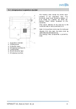
Page 9: ...er 3 Vent cock 4 Pressure line shut off valve 1 female 5 Pump controller 6 Pressure sensor 4 20 mA male 7 Separation chamber 8 Stopcock for mains water 3 4 female 9 Mains water floating valve 10 3 2 w...

Page 10: ...he requirements of the following EU directives EG Directives for machines 89 392 EWG in accordance with 91 368 EWG EG Low voltage directives 73 23 EWG EG Directives for electromagnetic compatibility 8...

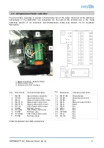
Page 11: ...lization or after a RESET STOP STOP instantaneous stop of the pump 5 Overview of components The SMT F SC has a modular design Each component can be separately exchanged 5 1 Components of the pump cont...

Page 12: ...steady Pump stopped due to flow rate below defined minimum see setting F1 Yellow flashing Minimum flow rate reached defined time delay is active see setting F14 Dry Working Dry Working Red flashing P...

Page 13: ...e disconnected and you have to wait for at least 2 minutes until all LEDs turn off internal capacitors are discharged You may open the case only after this To do this you have to demount the complete...

Page 14: ...hts up one time from 0 all the way to 10 bar and the pump stops LED Minimum Flow lights up 5 The self initialization is now finished and the start up procedure can follow see section 7 2 Changing the...

Page 15: ...n of setting mode STOP press simultaneously for about 3 seconds until the total segmented LED indicator blinks once and the setting F1 is displayed Display next setting value Keep the STOP button pres...

Page 16: ...on direction 0 1 0 1 0 F6 Starting RPM ramp up RPM during acceleration 1000 10000 RPM s Each step 500 3000 RPM s F7 Maximum operating pressure Maximum system pressure that should not be exceeded 2 10...

Page 17: ...h step 1 sec 12 sec F16 Dry running time delay Setting for time delay on the dry running condition before stopping pump 10 100 sec Each step 5 sec 40 sec F17 Master Slave group communication Operating...

Page 18: ...e Connection description Pos Board code Connection description 1 2 3 4 5 6 7 8 9 10 11 NE PE ST PE NE bl NE ST bl NE ST br ST1 br PUIN1 ST2 grey PUIN2 ST3 black PUIN3 Ground mains connection Ground pu...

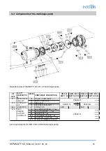
Page 19: ...DED 1 pcs 1 380 CAPACITOR 47 CAPACITOR ZBR 1 ZBR 1 16 16 O RING NOZZLE 1 pc 1 84 84 PLUG FRONT 1 pc 1 88 88 SHUTTER 1 pc 1 490 490 RUBBER SPACER 1 pc 1 89 89 SPRING SHUTTER 1 pc 1 370 370 SELF PRIMING...

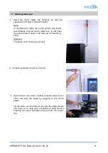
Page 20: ...g valves closed backside of the container The correct distance of the float 5 to the horizontal lever is factory set at 8 5 cm Note If an overflow occurs due to continuous dripping from the valve the...

Page 21: ...C is mounted on a wall with the supplied wall bracket The lid and lateral distances indicated should be adhered to when mounting to provide clear maintenance access The SMT F SC is wall mounted in suc...

Page 22: ...ly is done with the provided flexible hose and stopcock Screw the gland screw into the chamber connection and carefully tighten with a fixed wench Note The flexible hose must not be overtightened as t...

Page 23: ...nnected to the pump controller The flexible hose and the shut off valve then connect to the pressure line set and the pressure line Attention For optimal and efficient pressure control an expansion ve...

Page 24: ...ecting to a drainage system in order to prevent backflow of drainage water from the open sewer line design according to the DIN EN 1717 entering the SMT F SC The position of the backwater level determ...

Page 25: ...n this case the pump doesn t need to be filled up with water by hand Attention The pump must not be dry running 2 Close the pressure line shut off valve 3 Open the air vent hold a bucket of water unde...

Page 26: ...e all the fixtures The pump will now automatically switch off when the maximum system pressure is reached The green LED on the pump controller indicates that the pump is ready to use In case of a prob...

Page 27: ...defined by I2t algorithm to protect the motor insulation for correct functioning the rated current must be set F2 A6 Pressure switch malfunction In case of a problem or failure of the pressure switch...

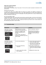
Page 28: ...will follow After 5 trials the alarm indicator will become permanent and a manual restart will be necessary press STOP then START 9 Trouble shooting Description Cause Solution Pump does not start Dry...

Page 29: ...r is in the separation chamber Check mains water pressure clean the filter sieve in the mains water valve see section 5 4 10 Maintenance The SMT F SC operates without regular maintenance At minimum ch...

Page 30: ...r customers in Germany For any queries ordering of spare parts as well as in case of service kindly contact INTEWA GmbH directly quoting your product s model and identification numbers and the purchas...

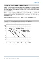
Page 31: ...ever fail the others simply take on the load Through Bluetooth the automatic cycling start up of the pumps the peak load connection and the operating pressure settings are aligned and transferred wir...

Page 32: ...to use The pumps will automatically start as soon as a decrease in pressure is detected 4 The desired operating pressure can be adjusted by pressing or on any one pump controller The Bluetooth connec...

Reviews: