background image


Accusafe Sensor Module User Manual 

17 

06/21/2021 


The following parameters are displayed and/or accessed/changed on this screen: 


Controller IP

: The existing IP address for the F901 controller. 


Software  Version

:  The  current  software  version.  Software  version  can  be  updated  via  the 

LAUNCHER APP That accompanies your system on a flash drive.  See section 4 on the next 
page for details on using the LAUNCHER APP. 


Storage  Usage

:  Current  controller  disk  usage.  The  controller  keeps  all  sensor  data  in  its 

internal drive. If the storage is full, you have the option to clean up recorded data using the 
LAUNCHER APP. See section 4.3.1 on page 20 for details on using the LAUNCHER APP. 


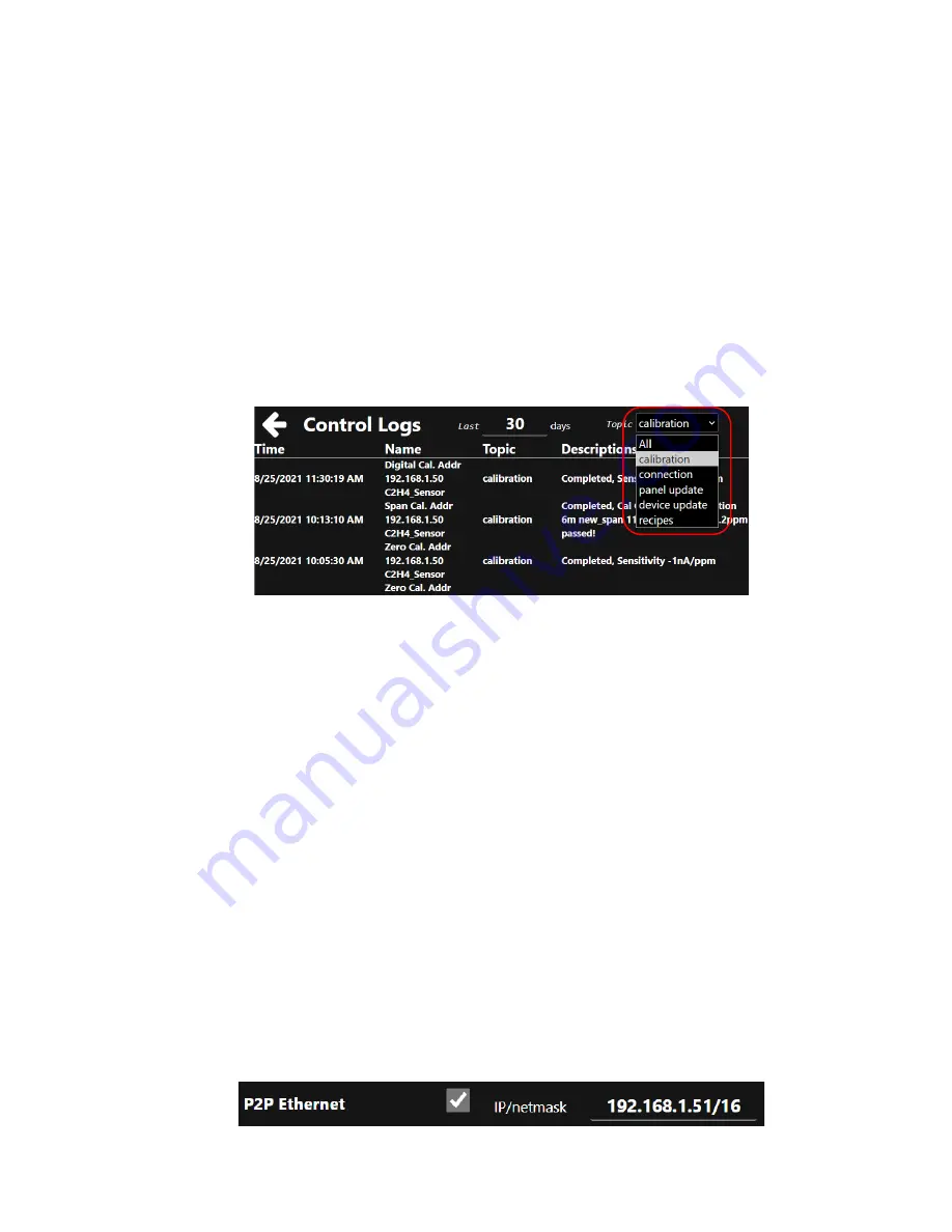
Control Logs 

– Tapping the Control Logs icon opens the Control Logs screen shown below. 

This provides access to activity logs relating to the items shown in the 

“topic” drop down menu 

circled in red. Select the desired category or 

“All” then enter the days period of interest in the 

“Last__ days” field. The screenshot below shows logs for Calibration activity over the past 30 
days. If entries exceed display area, scrolling down will display additional entries.  


Controller name

Default name is “F901 Controller”. You can rename the device if desired by 

touching the name text field and entering a new name using the pop up keyboard. Be sure to 
save changes by touching “SAVE” at the bottom of the screen. 


Display Chart Length

: This value represents the amount of time displayed horizontally on the 

Sensor  Measurements  Panel  graph  displays.  This  value  can  be  changed  by  touching  the 
numeric field and entering a new value on the pop-up numeric window. Save any changes by 
touching the SAVE button at the bottom of the screen.  


Advanced UI

: Switch between advanced UI and simple UI. Simple UI removes a number of 

features from the display. Advanced UI is the recommended selection.  


PID Tuning

: Enables PID tuning parameters in the Control Panels menu. This is enabled but 

generally not used in the ACCUSAFE systems. 


Enable MQTT

: Enables remote access to controller via cloud services. Save any changes by 

touching the SAVE button at the bottom of the screen. See section 4.3.5 on page 23 for more 
on this feature. 


Light Theme

: When  checked,  changes  screen background  to  white  instead  of  black.  Save 

any changes by touching the SAVE button at the bottom of the screen.  


P2P Ethernet

: This should be checked if connecting directly via Ethernet to a single sensor 

module or other device (point-to-point) without the use of a hub. Selecting P2P will enable the 
option to configure the controller

’s own IP address as shown below. Enter the address shown: 


Summary of Contents for ACCUSAFE F901

Page 1: ...Interscan Corporation Instruction Manual ACCUSAFEF901ControllerModule...

Page 2: ...verview 7 3 1 1 Controller Toolbar 7 3 1 2 Control Panels 7 3 1 3 Sensor Measurements 10 3 1 4 Alarms 12 3 1 5 Recipes 14 3 1 6 Panel Configuration 14 3 1 7 Sensor Calibration 16 3 1 8 Info 16 Section...

Page 3: ...p the device The power connector will not make connection to GND if not fully plugged into the socket Do not expose this device to any liquids Power Input 5V DC Avg Power Consumption 5W Weight 0 88 kg...

Page 4: ...ct to the comm port on the ACCUSAFE Sensor module for single sensor applications or to an Ethernet switch or hub for multi sensor applications For RTU RS485 communications applications connect a stand...

Page 5: ...faced with the sensor s See section 3 2 of the F901B Sensor Module user manual for details on sensor Modbus setup and implementation 3 2 1 RTU RS485 CONFIGURATION RS485 cabling configuration is shown...

Page 6: ...at A and B 8kV 3 2 2 EXAMPLE MODBUS CONFIGURATION Figure 2 1 Hub connection configuration NOTE 1 See Section 3 1 8 on page 16 for details on switching between Hub and Direct Ethernet connection via P...

Page 7: ...Accusafe Sensor Module User Manual 6 06 21 2021 NOTE 2 Refer to the F901B Sensor Module user manual for details on Sensor module setup and interfacing with the F901 Controller...

Page 8: ...ted by a blue highlighted icon on the toolbar 3 1 2 CONTROL PANELS All elements controlled and displayed by the controller are organized into Panels that determine all the parameters associated with t...

Page 9: ...which contains a slider controller for changing the value associated with the pump speed See Figure 3 5 on page 10 for details on the PUMP CNTRL panel All ACCUSAFE instruments will contain the followi...

Page 10: ...lly for each sensor module in the network See figure 3 4 below One PUMP CONTROL panel containing one pump control slider for each F901B sensor module allowing the user to raise or lower the pump speed...

Page 11: ...the display panel typically viewed during normal operation This panel will contain a numeric and graphical display of all data from the panels enabled in the Control Panels menus Typically this will...

Page 12: ...lay shows the real time value and all graphical data is displayed oldest to newest from left to right FIGURE 3 7 Enabling more data panels will effectively squeeze the existing graphs into less vertic...

Page 13: ...indow and enter the desired value Less Than setting change this value to set the alarm level BELOW which the alarm will activate for the panel device EX Set the H2S 2 level at 20 0 PPM for an alarm ac...

Page 14: ...gs screen FIGURE 3 11 Example Alarm Panel When alarm conditions are active there will be a visual indication on the Sensor Measurement screen next to the sensor label as shown below Alarm on H2S 2 cha...

Page 15: ...be to rename the gas sensor channels to better reflect the locations they correspond to Figure 3 13 below shows the Sensor Measurement screen shown earlier with renamed gas sensor channels These new...

Page 16: ...the OK button on the confirmation screen that appears 3 Save the panel changes by touching the Save Panel button shown above circled in yellow followed by touching the OK button on the confirmation s...

Page 17: ...ibration options for each sensor module in the system as shown below in Figure 3 18 The Calibration procedures are detailed fully in Section 4 of the F901B Sensor Module User Manual Refer to this manu...

Page 18: ...evice if desired by touching the name text field and entering a new name using the pop up keyboard Be sure to save changes by touching SAVE at the bottom of the screen Display Chart Length This value...

Page 19: ...tion which is provided on a USB drive with your system This app also provides access to downloading of data and saving loading of the controller setup The Launcher app is provided as a simple exe file...

Page 20: ...n the Files tab in the menu at the top then click on Add Controller as shown to the right In the Add a device window that opens as shown to the right enter the controller s IP address This address can...

Page 21: ...hown below From here you can carry out all the same functions described earlier in section 3 1 4 3 1 DOWNLOAD DATA To download device data to computer in CSV Excel format Click on the Download Data bu...

Page 22: ...ng the interval value and units value desired from the 2 dropdown menus circled below Or leave the Group by time box unchecked to download ALL available data for the devices and time span selected Whe...

Page 23: ...r can edit and or save existing panel configurations and open edit previously saved configurations in the editor and upload them to the controller A typical editor window is shown below A common use o...

Page 24: ...anel configuration on your computer 4 3 4 SOFTWARE UPDATE This feature allows the user to upload any new controller software revisions from a saved location on their computer To access this feature cl...

Page 25: ...d service account If your cloud service uses SSL TLS connection obtain and save the secure certificate Private key and CA Certificate files to your computer Enter your cloud Server name If using SSL T...

Page 26: ...ample API call from paho mqtt client Client subscribe topic F901 controller EP0 qos 0 Example return topic F901 controller EP0 payload id1556576356539 enable false name Generator Manual devices id1556...

Page 27: ...03 attr controllerEnable value False disable panel client publish topic F901 controller EP1 payload json dumps msg device_param set a device in a panel parameter Applicable for actuator devices only i...

Page 28: ...User Manual 27 06 21 2021 Section 5 Calibration Calibration of the Accusafe system is fully detailed in section 4 of the dedicated Accusafe Sensor Module manual Refer to that manual for details on all...

Page 29: ...k all cable connections for firm connection Power down both the Sensor module and the Controller Wait several seconds then power up the Sensor module followed by the Controller one minute later Power...

Page 30: ...ed or altered by unauthorized persons or which have been subject to misuse negligence or accident incorrect wiring by others installation or use not in accordance with instructions furnished by the ma...

Reviews: