33
User Manual
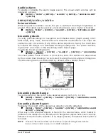
Audible Alarm
To enable or disable the alarm beeps sound. The visual alarm window will be
displayed anyway.
[MENU] + "MENU" + [ENTER] + "ALARMS" + [ENTER] + "AUDIBLE ALARM"
+ [ENTER]
CM V6/V6i/11CV+/11CVS+:
External Alarm
When any alarm condition occurs the pin is switched from High Impedance to
ground. This signal can be used by an external device (as a hooter or buzzer).
[MENU] + "MENU" + [ENTER] + "ALARMS" + [ENTER] + "EXTERNAL ALARM"
+ [ENTER]
Grounding Alarm
To verify potential danger to navigation such shallow water (depth areas), inter-
tidal areas, land, rocks, obstructions and shoreline constructions. The maps are
scanned every 10 seconds. If any of the above objects are found, the chart plot-
ter notifies the danger on a dedicated warning message box. The active "Ground-
ing Alarms" are shown in the Grounding Alarm Report page.
To activate the Grounding Alarm:
[MENU] + "MENU" + [ENTER] + "ALARMS" + [ENTER] + "GROUNDING
ALARM" + [ENTER]
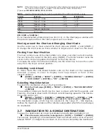
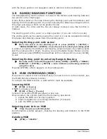
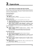
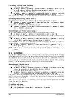
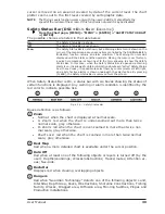
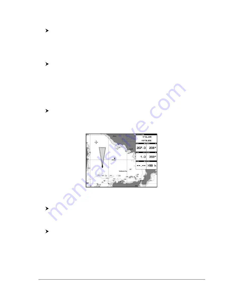
The chart plotter scans a sector in front of the boat. The direction is determined
by the current boat heading. You can select the length and its angle is 30 degrees.
The Grounding Alarm is switched Off by default after a Master Reset.
Fig. 3.9 - Grounding Alarm sector
Grounding Alarm Range
To set the length of the sector to be detected among 0.25, 0.5, 1.0 Nm.
[MENU] + "MENU" + [ENTER] + "ALARMS" + [ENTER] + "GROUNDING ALARM
RANGE" + [ENTER]
Grounding Alarm Report
To display the report of the dangerous objects currently detected.
[MENU] + "MENU" + [ENTER] + "ALARMS" + [ENTER] + "GROUNDING ALARM
REPORT" + [ENTER]
When any of the searched objects is found in the scanned area, a tick marker is
printed on the relative box to identify which dangerous objects have been currently
detected. Once the alarm condition is no longer present, the relative tick marker is
removed.
NOTE
The alarm "No data available" is shown when no specific cartographic data are
found on the C-CARD or when no C-CARD is inserted.
Summary of Contents for Chart Master 169CSI
Page 14: ...16 User Manual...
Page 34: ...36 User Manual...
Page 54: ...56 User Manual...
Page 72: ...74 User Manual...
Page 78: ...80 User Manual...
Page 81: ...83 User Manual INSTALLATION AND REMOVING EXTERNAL WIRING...
Page 84: ...86 User Manual...
Page 86: ...88 User Manual Dimensions...

