background image

OWNER’S MANUAL                                                            Ductless Split System  

 DLC4(A/H), DLF4(A/H)

14                                                                                                                                                 421 02 9218 00

CLEANING, MAINTENANCE, AND TROUBLESHOOTING

ELECTRICAL SHOCK HAZARD

Failure to follow this caution may result in personal

injury or death.

Always turn off power to the system before

performing any cleaning or maintenance to the

system. Turn off the outdoor disconnect switch

located near outdoor unit. Be sure to disconnect

indoor unit if on a separate switch.

CAUTION

!

EQUIPMENT DAMAGE/OPERATION  HAZARD

Failure to follow this caution may result in equipment

damage or improper unit operation.

Operating the system with dirty air filters may damage

the indoor unit and could cause reduced cooling

performance, intermittent system operation, frost

build

up on indoor coil or blown fuses.

CAUTION

!

Periodic Maintenance

Periodic maintenance is recommended to ensure proper

operation of the unit. Recommended maintenance intervals

may vary depending on the installation environment, e.g.,

dusty zones, etc. Refer to Table 1.

CUT  HAZARD

Failure to follow this caution may result in personal

injury. The coil fins are very sharp. Use caution when

cleaning.

CAUTION

!

Cleaning the Coil

Clean the coil at the beginning of each cooling season, or

when necessary. Use a vacuum cleaner or a long

bristle

brush to avoid damage to the coil fins.

Air Filters

Remove and clean the air filters once a month.

NOTE: 

If air filters show signs of excessive wear or are torn,

they must be replaced. Contact your local dealer for

replacement filters.

1. Open front panel on unit.
2. Pull filters down to remove.
3. Vacuum filters.
4. Clean with warm water.
5. Shake filter to remove excess water and dry

thoroughly.

6. Replace filter by sliding filter behind front grille until

filter snaps in place.

7. Close front panel on unit.

EQUIPMENT DAMAGE HAZARD

Failure to follow this caution may result  in equipment

damage.

When cleaning the front panel, do not use water

hotter than 105

_

F (40.56

_

C) and do not pour water

onto the fan coil. Do not use abrasive or petroleum

based cleaners as they may damage the front panel.

CAUTION

!

Indoor Unit Front Panel

To clean the front panel on the indoor unit, wipe the outside

with a soft, dry cloth. If necessary, a mild liquid detergent

can be applied and wiped off with a dry cloth.

Preparing for Extended Shutdown Period

Clean the filters and reposition them in the unit. Operate the

unit in Fan only mode for 12 hours to dry all internal parts.
Turn main power supply off and remove batteries from the

remote control.

System Operation Recommendations

The items outlined in the following list will help to assure

proper system operation:

S

Replace both remote control batteries at the same time.

S

Point the remote control toward the unit display panel

when transmitting a command.

S

Keep doors and windows closed while unit is operating.

S

Contact an authorized service representative if a

problem arises that cannot be easily resolved.

S

Do not perform cleaning or maintenance activities while

unit  is on.

S

Keep display panel on unit away from direct sunlight and

heat as this may interfere with remote control

transmissions.

S

Do not block air intakes and outlets on the indoor or

outdoor units.

Energy Saving Recommendations

The following recommendations will add greater efficiency to

the ductfree system:

S

Select a comfortable thermostat setting and leave it at

chosen setting. Avoid continually raising and lowering

the setting.

S

Keep unit filter clean. Frequent cleaning may be

necessary depending on indoor air quality.

S

Use drapes, curtains or shades to keep direct sunlight

from heating room on very hot days.

S

Do not obstruct air intake on front panel.

S

Turn on air conditioning before indoor air becomes too

uncomfortable.

Troubleshooting

Refer to Table 2 before contacting your local dealer.

Summary of Contents for DLC4A

Page 1: ...ormation Manual carefully before installing and using this appliance and keep this manual for future reference For your convenience please record the model and serial numbers of your new equipment in the spaces provided This information along with the installation data and dealer contact information will be helpful should your system require maintenance or service UNIT INFORMATION Model __________...

Page 2: ...s product WARNING GENERAL The high wall fan coil unit provides quiet maximum comfort In addition to cooling and or heating the high wall fan coil unit matched with an outdoor condensing unit will filter and dehumidify the air in the room to provide maximum comfort IMPORTANT The high wall fan coil unit should be installed by authorized personnel only using approved tubing and accessories If technic...

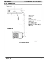
Page 3: ...r Outdoor Unit A08294a 1 Front Panel Frame 2 Display Panel 3 Front Panel 4 Air Filter 5 Horizontal Airflow Louver 6 Manual Adjustable Vertical Airflow Louver 7 Remote Control 8 Room Temperature Sensor 9 Inter Connecting Tubing 10 Control and Power Wiring to Indoor Unit 11 Service Valves 1 2 3 4 5 6 7 8 9 10 11 ...

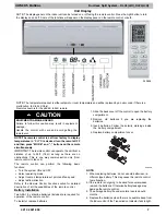
Page 4: ... Button to Turn ON or OFF Display on Front Panel 1 2 3 4 5 6 7 8 9 10 11 12 13 14 Remote Control Size 30 36 1 Remote Control Display 2 ON OFF Button 3 MODE Button 4 Setpoint Timer Up and Down Buttons 5 Fan Speed 6 Horizontal Louver Swing Button 7 Left Right Louver Swing Button Not available with these models 8 HEALTH SAVE Button Not available with these models 9 Dry Coil Button 10 Temperature Butt...

Page 5: ...TURE DISPLAY Temperature setting from 61_F 16_C to 86_F 30_C will be displayed If FAN mode is selected there will be no temperature displayed 7 CLOCK DISPLAY Indicates the current time 0 to 24 hours 8 CLOCK INDICATOR Displayed with time and is not displayed when setting ON OFF timer 9 TIMER ON TIMER OFF DISPLAY ON is displayed if TIMER ON is set OFF is displayed if TIMER OFF is set ON OFF displaye...

Page 6: ...nt operation mode AUTO COOL DRY FAN ONLY or HEAT 5 SLEEP DISPLAY Indicates unit is running in SLEEP mode 6 TEMPERATURE DISPLAY Temperature setting from 61_F 16_C to 86_F 30_C will be displayed If FAN mode is selected there will be no temperature displayed 7 Left Right Louver Swing Not available on these models 8 Health Save Not available on these models 9 SETTING ON OFF TIMES 0 5 to 24 hours 10 TU...

Page 7: ...only from remote control to fan coil The remote control can perform the following basic functions S Turn the system ON and OFF S Select operating mode S Adjust room air temperature set point and fan speed S Adjust airflow direction Refer to the Remote Control Function section for detailed description of all the capabilities of the remote control Battery Installation Two AAA 1 5 v alkaline batterie...

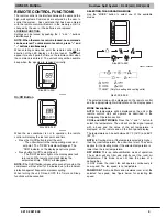
Page 8: ...t will confirm receipt of a command by sounding an audible beep 1 Turn the unit on by pushing the ON OFF button 2 Select the desired mode by pushing the mode button Size 9K to 24K Size 30K to 36K Only for heating and cooling units Only for heating and cooling units A08301 3 Select the temperature set point by pointing the control toward the unit and pressing the or buttons until the desired temper...

Page 9: ...nt and time OPER will disappear NOTE If the On Off button is pressed too soon after a stop the compressor will not start for 3 minutes due to the inherent protection against frequent compressor cycling When turning the unit ON and OFF the Timer and Sleep functions will be cancelled SELECTING THE OPERATING MODE Use the MODE button to select one of the available modes Size 9K to 24K A09641 A09628b S...

Page 10: ...n the TEMP button is pushed a second time a thermometer is displayed inside the temperature indicator This indicates that the room temperature is displayed on the front panel NOTE If any other button is pushed on remote control the temperature will return to the setpoint temperature Outdoor air temperature is not available Using Dry Coil Function X Fan When operating in humid areas hi wall units h...

Page 11: ...e user to select the swing or a stationary position To change the louver position press the SWING button once The icon will be displayed on the remote Swing Icon Size 30K 36K The louver will swing continuously If the SWING button is pushed again the louver will stop in its present position If the user prefers to select swing with 5 preset stationary positions follow the instructions below S Turn O...

Page 12: ... only OPER ºF ºC HOUR OFF Only OFF is displayed A09642 This function will allow the unit to stop automatically at the set time The timer can be set while the unit is on or while it is off To set the TIMER OFF function perform the following 1 Push the TIMER OFF button once 2 The clock indicator and time will not be displayed OFF will be flashing 3 Push the or button within 5 seconds until the desir...

Page 13: ... the indoor unit front panel ON or OFF The remote control will display the Light Icon as shown below Light Icon Size 30K 36K Size 9K to 24K Light Icon Time Delay If the On Off button is pressed too soon after a stop the compressor will not start for 3 minutes due to the inherent protection against frequent compressor cycling The unit will only emit an audible beep when the signals are received cor...

Page 14: ...ilure to follow this caution may result in equipment damage When cleaning the front panel do not use water hotter than 105_F 40 56_C and do not pour water onto the fan coil Do not use abrasive or petroleum based cleaners as they may damage the front panel CAUTION Indoor Unit Front Panel To clean the front panel on the indoor unit wipe the outside with a soft dry cloth If necessary a mild liquid de...

Page 15: ...einsert plug Restart unit Water leaks into room from Indoor unit Condensing water has overflowed Check indoor condensing drain or call your representative Unit System Does Not Work To protect the unit upon an immediate restart after a stop the system controller will delay the unit for 3 minutes before allowing the unit to start back up The circuit breaker has tripped or a fuse has blown Power fail...

Reviews: