background image

Intermec EasyCoder PC41—Service Manual 

15 

Chapter 3—Top Cover

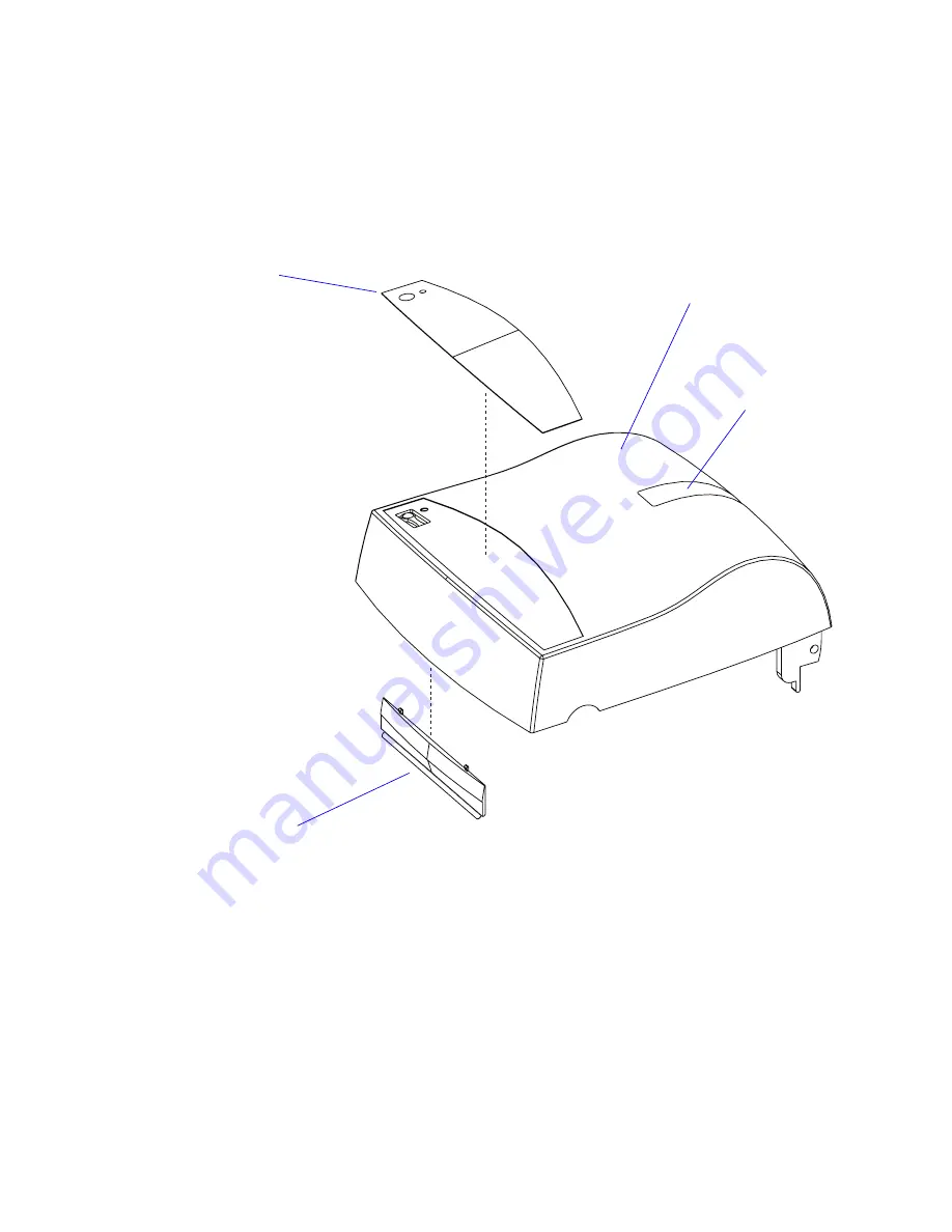
The top cover is made up of the following parts:
•  Top cover plastic moulding
•  Clear plastic window (permanently glued to the moulding)
•  Two media load instruction labels
•  Tear-off plate (snap-locked to the moulding)
•  Name plate (glued to the moulding)

3.2 Tear-Off Plate

The only part that can be replaced easily is the tear-off plate. It is provided 

with two snap-lock tabs that engage bars at the inside of the top cover. Two 

L-shaped rails hold the plate. If you need to remove the tear-off plate with-

out discarding it, be careful not to break the tabs, which are quite delicate. 

Top cover moulding

Clear window

Tear-off plate

Name plate

Summary of Contents for EasyCoder PC41

Page 1: ...Service Manual EasyCoder PC41 Bar Code Label Printer ...

Page 2: ...re subject to change without notice 2005 by Intermec Technologies Corporation All Rights Reserved EasyCoder EasyLAN Fingerprint and LabelShop are registered trademarks of Intermec Tech nologies Corp The word Intermec the Intermec logo InterDriver and PrintSet are trademarks of Intermec Technologies Corp The name Centronics is wholly owned by GENICOM Corporation Throughout this manual trademarked n...

Page 3: ...3 Top Cover 13 3 1 Description 14 3 2 Tear Off Plate 15 4 Print Frame 17 4 1 Description 18 4 2 LED and Feed Switch 19 4 3 Top Cover Locks 21 4 4 Base Lock Spring Hooks 21 4 5 Printhead 22 4 6 Ribbon End Sensor 25 4 7 Label Gap Sensor Emitter 27 4 8 Ribbon Feed Mechanism 28 5 Base Frame 33 5 1 Main Parts 34 5 2 Main Board 35 5 3 Platen Roller 36 5 4 Peel Off Mechanism 37 5 5 Motor assy 39 5 6 Media ...

Page 4: ... 54 7 6 Internal Memory 55 7 7 Schematics 56 8 Power Supply 61 8 1 Description 62 9 Memory Cartridge option 63 9 1 Description 64 9 2 Memory Sizes 65 9 3 Schematics 66 10 Starting Up 67 10 1 Overview 68 10 2 Normal Mode 70 10 3 Factory Default Mode 70 10 4 Test Mode 70 10 5 Dump Mode 71 11 Firmware Upgrading 73 11 1 Requirements 74 12 Troubleshooting 75 12 1 Checklist 76 ...

Page 5: ...ions Intermec EasyCoder PC41 Quick Start Guide multilingual Intermec EasyCoder PC41 User s Guide Intermec EasyCoder PC4 PC41 Spare Parts Catalog The IPL Programmer s Reference Manual Jan 2005 revision Please note that the operations described in this manual only should be car ried out by skilled and authorized personnel with proper training and full understanding of written English Moving parts ma...

Page 6: ...propriate measures needed to correct the problem DOC Notice Canada Canadian Dept of Communication REGULATIONS COMPLIANCE DOC A This digital apparatus does not exceed the class A limits for radio noise emissions from a digital apparatus as set out in the radio interference regu lations of the Canadian Department of Communication Ministère des Communications du Canada CONFORMITE DE REGLEMENTS DOC A ...

Page 7: ...Intermec EasyCoder PC41 Service Manual 1 1 Models and Options This chapter provides information on the various models of the EasyCoder PC41 and contains specifications and physical measures ...

Page 8: ...er PC41 has a separate power supply unit that delivers 24 VDC to the printer s main board where it is transformed to the various voltages required by the printhead motor and logics see Chapter 8 1 The power supply unit PSU accepts 100 to 240 VAC 50 to 60 Hz The power supply has a standard 2 pin input voltage socket so various types of power cords can be used according to local voltages and standar...

Page 9: ... 2 Options The available options for the EasyCoder PC41 are serial and parallel inter face cables a memory cartridge a paper cutter a battery unit and an assort ment of power cords Refer to the EasyCoder PC41 Spare Parts Catalog or Spare Parts List for updated information ...

Page 10: ... Outer max 41 mm 1 6 inches Ribbor Roll Core Diameter Inner 13 mm 0 5 inches Print Directions 4 Modes of Operation Tear Off Straight through Yes Peel Off Self strip Yes Cut off Yes Requires optional cutter Firmware Operating System Intermec Programming Language IPL Fonts 21 bitmap 3 outline resident fonts Font Magnification Horizontal max 999 times vertical max 999 times up to a maximum size of 4 inch...

Page 11: ...s TTR model only Controls Control Lamps 1 Tri colored LED Feed Button 1 Data Interfaces Serial 1 RS 232 Parallel 1 Centronics Accessories and Options Parallel Interface Cable Standard RS 232 Cable Option Memory Cartridge Option 1MB flash Paper Cutter Option V spring for stiff thick media Option Mobile Battery Unit Option Battery Pack Option Battery Charger Option ...

Page 12: ...6 Intermec EasyCoder PC41 Service Manual Chapter 1 Models and Options 259 mm 10 20 in 166 mm 6 54 in 314 mm 12 36 in 333 mm 13 11 in 1 4 EasyCoder PC41 Measures Side View ...

Page 13: ...Intermec EasyCoder PC41 Service Manual 7 Chapter 1 Models and Options 50 mm 1 97 in 133 mm 5 24 in 77 mm 3 03 in Front View Rear View ...

Page 14: ... Service Manual Chapter 1 Models and Options 230 mm 9 06 in 188 mm 7 40 in 39 mm 1 54 in 17 mm 0 67 in 9 mm 0 35 in 168 mm 6 61 in 209 mm 8 83 in 150 mm 5 91 in 4 6 mm 0 18 in 184 mm 7 24 in 154 mm 6 06 in Top View Bottom View ...

Page 15: ...r PC41 Service Manual 9 2 Main Parts This chapter shows the printer s main parts and explains how the printer is taken apart and reassembled Each of the main parts is described in more detail in the chapters that follow ...

Page 16: ...ect a number of cables from the main board In most cases you do not need to dismantle the base frame print frame and top cover In the illustration in Chapter 2 3 all cables have been omitted Detailed descriptions of the main parts and their sub assemblies can be found in Chapters 3 to 7 All screws are Phillips type of various sizes 2 2 Reassembling the Printer Reassemble the printer in reverse ord...

Page 17: ...Intermec EasyCoder PC41 Service Manual 11 Chapter 2 Main Parts 2 3 Exploded View Top Cover Print Frame Base Frame Bottom Cover Bolts E ring E ring ...

Page 18: ...12 Intermec EasyCoder PC41 Service Manual Chapter 2 Main Parts ...

Page 19: ...Intermec EasyCoder PC41 Service Manual 13 3 Top Cover This chapter describes the parts of the top cover and explains how to replace the tear off plate ...

Page 20: ...The top cover and the print frame opens together when the base locks on either side of the printer are pressed Then the top cover can be released from the print frame by pressing the two green locks at either side of the print frame as shown below Note that in case of a PC41 DT printer the locks are cut off and you will need to insert a flat screwdriver or similar to release the locks Base locks Top...

Page 21: ...snap locked to the moulding Name plate glued to the moulding 3 2 Tear Off Plate The only part that can be replaced easily is the tear off plate It is provided with two snap lock tabs that engage bars at the inside of the top cover Two L shaped rails hold the plate If you need to remove the tear off plate with out discarding it be careful not to break the tabs which are quite delicate Top cover mouldi...

Page 22: ...16 Intermec EasyCoder PC41 Service Manual Chapter 3 Top Cover ...

Page 23: ... Frame This chapter describes the print frame which contains the thermal print head the transfer ribbon supply the LED control lamp the Feed key and the emitter of the label gap sensor It also provides instructions for how to replace the various parts ...

Page 24: ...d with a 203 2 dpi 8 dots mm printhead Direct Thermal DT Model Thermal Transfer TTR Model Print frame moulding LED control lamp Feed switch No ribbon load label No transfer ribbon mechanism No ribbon end sensor Short top cover locks Print frame moulding LED control lamp Feed switch Ribbon load label Transfer ribbon mechanism Ribbon end sensor Long top cover locks Printhead Printhead Label gap sens...

Page 25: ...t window and the Feed switch is activated via a dome both in the name plate on the top cover Replacement The Feed Switch PCB can be accessed for replacement by removing the cable cover which is held in place by a Phillips screw and a snap lock The Feed Switch PCB is inserted between two rails in the moulding and is cov ered by an isolation sheet Green solid Ready Green flashing Receiving data Red s...

Page 26: ...20 Intermec EasyCoder PC41 Service Manual Chapter 4 Print Frame Schematics JP1 1 2 3 4 LED1 RED SW1 LED1 YELLOW R1 R2 ...

Page 27: ... cable cover as shown in the instructions for replacing the Feed Switch PCB earlier in this chap ter 4 4 Base Lock Spring Hooks Description Two spring hooks that are engaged by the base lock see Chapter 5 7 are fitted to the print frame moulding using Phillips screws The spring hooks are identical for the DT and TTR models Replacement The left side spring hook is fitted inside the same housing as th...

Page 28: ...er s Reference Manual Low ambient temperature requires more energy to the printhead dots than room temperatures and will therefore cause more wear to the print head High print speed accelerates the wear Thus at low temperatures select as low a print speed as is acceptable Never print outside the media path Dots that are not in contact with the media will not be cooled properly When using preprinte...

Page 29: ...pring Be careful not to touch the line of dots at the front of the printhead but press against the metal bracket or white plastic cover While keeping up the pressure slide the printhead forward so the tabs at both sides of the printhead bracket become disengaged from the pockets at the inner sides of the cavity in the print frame Continue to press forward so the U shaped slots in the sides of the ...

Page 30: ...thead kit comes as a complete unit including printhead bracket cover plate ground terminal screws and V spring Be careful not to touch the dots on the printhead and make sure that the tip of the V spring runs between the two guiding ridges on the printhead bracket Test that the printhead can move slightly up against the pressure force of the V spring Finally check that the printhead is working pro...

Page 31: ...lled in a pocket on the print frame moulding A cable runs inside the left side hinge of the print frame and down to the main board where it is connected to J5 The same circuit board is also used for the label taken sensor Refer to Chapter 5 2 for an description of how to access the main board Replacement Do not remove the sensor unless you intend to discard it since you may damage some of the comp...

Page 32: ...Intermec EasyCoder PC41 Service Manual Chapter 4 Print Frame Schematics RIBBON S01 S02 R2 R3 YES 150 100K YES 300 STRIPPER SW1 ON ENABLE OFF DISABLE ON OFF S02 1 2 3 4 5 R2 S01 1 2 3 4 C1 JP1 1 2 3 R3 SW1 ...

Page 33: ... washer in a pocket on the upper side of the print frame immediately to the rear of the ribbon slot In the TTR model the board is hidden under the ribbon load label The LED shines downward through a hole in the print frame moulding Before replacing the sensor check that the hole is not blocked by dust or similar The label gap sensor is connected to J3 on the main board via a cable running inside t...

Page 34: ...mechanism breaks the rotation of the ribbon supply spool in order to keep the ribbon tight using a spring loaded friction cou pling Another spring dampens sudden jerks The friction is affected by the position of the fixed holder along the ribbon supply shaft If you need to dismantle this assembly make sure that the ends of the short spring fit into the holes in the ribbon return cap and friction plat...

Page 35: ...cores opposite to the ribbon feed mechanism A green plastic disc is press fitted on a metal shaft that goes through the left side wall of the print frame moulding The shaft is held by an E ring inside the Feed button cavity A spring on the shaft makes it possible to snap the core in place No adjustments are facilitated E ring Washer Spring Ribbon core holder ...

Page 36: ...iction coupling similar to the ribbon supply A large green wheel which engages a one way clutch makes it easier to wind up the ribbon leader at ribbon load If you need to replace the right side base lock spring hook just remove the E ring and lift out the entire rewind assembly without dismantling it any further This way you will keep the factory adjustments Ribbon rewind shaft Fixed holder Screws...

Page 37: ...the ribbon takeup The rear gear engages the gear wheel of the ribbon takeup whereas the other gear engages the gear train in the base frame when the print frame is in closed and locked position This implies that the ribbon takeup can be rotated freely in both directions when the print frame is in open position but only in one direction when it is closed There are no facilities for adjustments Spri...

Page 38: ...32 Intermec EasyCoder PC41 Service Manual Chapter 4 Print Frame ...

Page 39: ...Intermec EasyCoder PC41 Service Manual 33 5 Base Frame This chapter describes the main parts of the base frame and provides replacement instructions ...

Page 40: ...ic moulding to which a number of assem blies are fitted The same base frame is used for both the DT and the TTR models of the EasyCoder PC41 The optional paper cutter is normally factory fitted but could be field installed by an authorized service technician see EasyCoder PC4 PC41 Cutter Installation Instructions It replaces the standard peel off mecha nism Media spindle Black mark Label gap sensor La...

Page 41: ... The main board is described in detail in Chapter 7 along with schematics and a connection diagram Replacement Take precautions to eliminate any electrostatic discharges Make sure the main board is disconnected from any power source Remove the single Phillips screw almost at the center of bottom side of the board Disconnect all cables to the main board Remove the nut at the top of the rear plate a...

Page 42: ...the platen cover and disengage the snap lock of the platen cover Pry up the platen cover Push the right side bushing to the right to disengage it Then using a moderate amount of force pry the bushing gear and platen roller upwards Lift out the platen roller and the left side bushing Replace with a new set of platen roller bushings and gear in reverse order Make sure that the D plane of the left si...

Page 43: ...taken sensor consists of an LED and a photoelectric sensor with an on off switch The light from the LED is reflected back to the sensor by the back side of any label or similar that remains to be removed from the outfeed area The sensor triggers at 4V which must drop to 1V before the sensor changes its state The same circuit board is also used as for ribbon detection Replacement The peel off mechanis...

Page 44: ...operator can enable disable the label taken sensor by manipulating the switch on the inside of the peel off mechanism as shown below Schematics OFF ON RIBBON S01 S02 R2 R3 YES 150 100K YES 300 STRIPPER SW1 ON ENABLE OFF DISABLE ON OFF S02 1 2 3 4 5 R2 S01 1 2 3 4 C1 JP1 1 2 3 R3 SW1 ...

Page 45: ... the platen roller The platen roller gear engages the ribbon takeup gear when the print frame is closed The stepper motor is connected to J2 and the thermistor to J4 on the main board Replacement The motor assy mechanism comes as a complete unit including stepper motor bracket thermistor gears washer E rings and nuts Disconnect the cables from J2 and J4 on the main board Remove the E rings washer ...

Page 46: ...25 mm 1 inch to 116 mm 4 57 inches Replacement The media guide assy mechanism comes as a kit as illustrated below Rotate the adjust knob to minimum media width Remove the screws that hold the label stoppers to the label guides and pull out the stoppers Remove the screw that holds the knob holder and take out the knob and holder Pull the gear away from the worm bushing Pull out the worn rod and the...

Page 47: ...int frame see Chapter 4 4 Note Parts are marked with L or R indicating left or right side When the print frame is closed the V spring ensures that the printhead is pressed against the platen roller with a sufficient force to provide a clear printout and to drive the media Replacement The base locks come as a kit with two complete assembled units one for each side Remove the screws that hold the lock...

Page 48: ...42 Intermec EasyCoder PC41 Service Manual Chapter 5 Base Frame ...

Page 49: ... 5 mm 0 177 inches Black Mark Sensor 10 mm 0 394 inches The board has one LED emitter and two receivers The black mark sensor emitter shines upwards The black mark sensor receiver detects light reflected by the back side of the media No light received is interpreted as a black mark The label gap sensor receiver detects light from the emitter board in the print frame see Chapter 4 7 that passes thro...

Page 50: ...44 Intermec EasyCoder PC41 Service Manual Chapter 5 Base Frame Schematics C1 S02 1 2 3 4 JP1 1 2 3 4 5 SO1 R2 R3 ...

Page 51: ... supply cavity The media spindle can be rotated to fit media cores with an inner diam eter of either 25 4 mm 1 inch or 38 1 mm 1 5 inches Text and arrows moulded into the spindle indicate core size in millimeters on one side and inches on the other As an alternative to using a media supply roll on the spindle fan folds or similar can be routed from an external supply behind the printer and into the...

Page 52: ...46 Intermec EasyCoder PC41 Service Manual Chapter 5 Base Frame ...

Page 53: ...Intermec EasyCoder PC41 Service Manual 47 This chapter describes the bottom cover and explains how to remove the accessory cover 6 Bottom Cover ...

Page 54: ...four Phillips screws An accessory cover which facilitates installation of an optional paper cutter is snapped locked to the bottom cover Four rubber feet are glued to the bottom plate which also has four screw pockets that allow the printer to be permanently attached to a table or similar Screw pockets Bottom cover Accessory cover Screw 4 Rubber foot 4 ...

Page 55: ...Intermec EasyCoder PC41 Service Manual 49 7 Main Board This chapter describes the main board including test points connections memory organization and schematics ...

Page 56: ... into a bitmap pattern that controls the heating of the dots on the print head which in turn creates the printout It also controls the media feed and detects various error conditions using the connected sensors and switches The main board has a memory where the user can store graphics and forms The memory can be expanded by fitting an optional memory cartridge directly to a connector on the main bo...

Page 57: ... frame and from the bottom cover Always disconnect the power supply and take precautions against elec trostatic discharges before touching the main board 7 3 Connections This simplified illustration shows where the various cables are connected to the main board PRODUCT REV NO On Off Switch J9 Printhead J8 Printhead J15 Centronics J13 RS 232 Printhead GND Power Supply J3 Upper Label Gap Sensor J7 Lo...

Page 58: ...r PC41 Service Manual Chapter 7 Main Board 7 4 Test Points PP7 PP11 PP13 PP62 PP73 PP75 PP107 PP48 PP115 PP117 PP124 PP162 PP164 PP176 PP179 PP191 PP201 PP216 PP221 PP226 PP228 PP235 Main Board test points on reverse side ...

Page 59: ...ort ACK PP115 PBUSY Parallel port busy PP117 STROBE Printhead strobe PP124 PERROR Paper error PP162 AN0 Gap sensor A D PP164 PCLK Printhead clock PP176 TXD RS 232 PP179 RXD RS 232 PP191 CTS RS 232 PP201 REFRESH DRAM refresh timer PP216 CASH DRAM PP221 CASL DRAM PP226 RAS DRAM PP228 RTS RS 232 PP235 16MHZ System clock 20MHz frequency J11 pin 5 RESET System reset J16 pin 1 5V Logic supply voltage J1...

Page 60: ...A D Converter U19 LEDs FEED J6 IEEE 1284 J15 RS 232 J13 Ribbon J5 GAP J3 J7 Black Mark J7 Strip J10 Motor Thermistor J4 PH Temp Thermistor Power Supply DC 24V 5V Power Input J14 ROM U3 U4 2M DRAM U5 512 K PLD U14 Print Head J8 J9 Spyder Debug J16 System Bus Motor Drivers U24 U25 PAL U23 FLASH Memory Expansion J12 Motor J2 Cutter J1 ...

Page 61: ...55 Chapter 7 Main Board 7 6 Internal Memory The EasyCoder PC41 has as a standard a DRAM memory of 512K and an EPROM memory of 2048K fitted on the main board The internal memory can be expanded using an optional memory car tridge see Chapter 9 ...

Page 62: ...7 A19 CS6 A1 A2 A3 A4 A5 A6 A7 A11 A12 A13 A14 A15 A16 A17 A18 VSS 15 1 A0 DSACK0 DSACK1 AVEC RMC DS AS SIZ0 SIZ1 R W RESET HALT BEER IRQ1 IRQ2 IRQ3 IRQ4 IRQ5 IRQ6 IRQ7 VSTBY FREEZE QOUT A8 A9 A10 MODCK PP142 PP224 R56 10K 0603 PP223 PP237 R65 10K 0603 R28 10K 0603 PP93 PP207 C55 150P 0603 R51 47ohm 0603 U18B 74S02 5 6 4 PP148 PP127 C68 68U E C U5 KM416C256 16 17 18 19 22 23 24 25 2 3 4 5 7 8 9 10...

Page 63: ...0 U16D 74HC05 9 8 U15E 74HC14 11 10 R9 22ohm 0603 U15F 74HC14 13 12 C33 150P 0603 C28 1U 25V 0603 R11 1K 0603 PP95 U8 74AHCT374 3 4 7 8 13 14 17 18 1 11 2 5 6 9 12 15 16 19 D0 D1 D2 D3 D4 D5 D6 D7 OC CLK Q0 Q1 Q2 Q3 Q4 Q5 Q6 Q7 U15D 74HC14 9 8 C23 150P 50V 0603 U15A 74HC14 1 2 C35 150P 0603 PP163 J15 1 2 3 4 5 6 7 8 9 10 11 12 13 14 15 16 17 18 19 20 21 22 23 24 25 26 27 28 29 30 31 32 33 34 35 36...

Page 64: ... P 9 0 1 R K 1 3 0 6 0 1 9 C F p 0 2 8 3 0 6 0 1 1 1 R m h o 5 0 W 1 P I D 1 8 R K 0 1 3 0 6 0 3 8 R m h o 6 2 2 3 0 6 0 2 8 R m h o 0 7 4 3 0 6 0 4 8 R m h o 0 0 1 3 0 6 0 7 7 C U 1 5 0 8 0 3 1 N R m h o 0 0 1 1 8 2 7 3 6 4 5 0 8 R m h o 7 4 3 0 6 0 3 0 1 R K 2 3 0 6 0 1 R V K 0 1 P I D 6 8 R K 0 1 3 0 6 0 9 7 R 7 K 4 3 0 6 0 2 0 1 R 7 K 4 3 0 6 0 4 0 1 R m h o 0 0 3 3 0 6 0 3 L H U 0 2 2 8 7 C V...

Page 65: ... 0 3 3 C E 1 J 6 N O C 1 2 3 4 5 6 6 9 C V 0 5 U 1 0 3 0 6 0 7 1 1 R 9 9 K 4 3 0 6 0 3 2 U C 8 V 6 1 F T A 1 1 1 2 1 3 1 4 1 5 1 6 1 7 1 8 1 9 1 0 2 0 1 2 3 4 5 6 7 8 9 K L C I E O I O I O I O I O I O I O I O I O I D N G C C V I I I I I I I I 9 C B F P 0 0 1 3 0 6 0 7 9 C V 0 5 U 1 0 3 0 6 0 9 9 C V 0 5 U 1 5 0 8 0 4 1 N R m h o 0 0 1 1 8 2 7 3 6 4 5 2 9 C V 0 5 U 1 3 0 6 0 6 D D 3 T 0 4 3 S R B M...

Page 66: ...60 Intermec EasyCoder PC41 Service Manual Chapter 7 Main Board ...

Page 67: ...Intermec EasyCoder PC41 Service Manual 61 8 Power Supply This chapter describes the separate power supply ...

Page 68: ...onnector that allows various types of power cords to be fitted depending on local standards A fixed cable with a length of 1 5 m 4 9 ft runs from the power supply to a connector on the printer s rear plate between the On Off switch and the parallel connector At the top of the power supply is a LED that indicates when the power supply is connected to an AC source Dangerous voltage The power supply mus...

Page 69: ...Intermec EasyCoder PC41 Service Manual 63 9 Memory Cartridge option This chapter describes the optional memory cartridge that can be used to expand the printer s built in memory ...

Page 70: ... inserted into a slot in the base frame after the print frame has been opened When no cartridge is used the slot is covered by a blind plate The switch on the short side of the memory cartridge controls a feature used exclusively in the EasyCoder PC4 printer Since this feature in incom patible with the PC41 the position of the switch is of no significance Mem ory Cartridge ...

Page 71: ...asyCoder PC41 Service Manual 65 Chapter 9 Memory Cartridge 9 2 Memory Sizes The memory cartridge provides the printer with an additional 1024 Kb of Flash memory that can be used to store forms graphics and fonts ...

Page 72: ... 21 20 19 18 16 17 NC A16 A14 A12 A7 A6 A5 A4 A3 A2 A1 A0 DO1 DO2 DO3 VCC A15 S2 W A13 A8 A9 A11 OE A10 S1 DO8 DO7 DO6 DO5 GND DO4 U3 1 2 3 4 5 6 7 8 9 10 11 12 13 14 15 32 31 30 29 28 27 26 25 24 23 22 21 20 19 18 16 17 NC A16 A14 A12 A7 A6 A5 A4 A3 A2 A1 A0 DO1 DO2 DO3 VCC A15 S2 W A13 A8 A9 A11 OE A10 S1 DO8 DO7 DO6 DO5 GND DO4 U2 1 2 3 4 5 6 7 8 9 10 11 12 13 14 15 32 31 30 29 28 27 26 25 24 2...

Page 73: ...ntermec EasyCoder PC41 Service Manual 67 10 Starting Up This chapter describes how the printer starts up in normal mode or test mode and how the printer automatically switches from test mode to dump mode ...

Page 74: ...or and hardware is initiated upon which the LED control lamp shines green and the configua tion is loaded The firmware checks if the Feed key is being pressed or not If the Feed key is pressed the printer will run a test to see if media is loaded If this is the case the printer will proceed into Test mode If not the printer will go into Factory Default Mode If the Feed key is not pressed the printer...

Page 75: ...e No Green LED on Orange LED flash Orange LED on Wait for media load and Feed to be pressed Red LED on Orange LED flash Wait for reboot Wait for Feed key press 8 secs Red LED flash Wait for Feed key to be pressed Orange LED flash Reset to Factory Defaults Factory Default Mode Print HW config label Green LED on Is Feed key Pressed Is data received on any port Suspend Dump Mode Print Data Print SW c...

Page 76: ...nter Test mode keep the Feed key pressed down while switching on the power Do not release the Feed key until the LED control lamp flashes orange The first thing that happens after you have entered the Test mode is that the printer feeds out one or two blank forms that is labels tags tickets etc followed by a label showing the printer s hardware configuration If you use longer forms you must set the c...

Page 77: ... the serial or parallel communication ports are printed on a single continuous row Each charac ter is printed along with its corresponding ASCII number between ASCII 000 dec and ASCII 255 dec To leave the Dump Mode briefly tap the Feed key without entering any characters This will cause the printer to proceed with its test sequence ...

Page 78: ...72 Intermec EasyCoder PC41 Service Manual Chapter 10 Starting Up ...

Page 79: ...Intermec EasyCoder PC41 Service Manual 73 11 Firmware Upgrading This chapter explains how to upgrade the printer with a later firmware version ...

Page 80: ...more information on how to obtain replacement EPROMs Step by Step Instructions 1 Disconnect the printer s power source 2 Flip the printer upside down and pry open the accessory cover using a small straight slot screwdriver 3 Locate the EPROM slots see below and remove the old EPROMs using a PLCC Extractor tool or equivalent 4 Insert the new EPROMs into their appropriate slots U3 and U4 respec tive...

Page 81: ...Intermec EasyCoder PC41 Service Manual 75 12 Troubleshooting This chapter list some possible error conditions and suggests remedies depending on the cause of the error ...

Page 82: ...efect Replace the Main board and try again Description LED on printer lights green but printer will not feed Possible Cause of Problem and Suggested Measures Label taken sensor active label not removed Remove label or disable the label taken sensor using the Self Strip command Connection error between printer and host Make sure correct type of interface cable is securely plugged into both printer ...

Page 83: ...bel Possible Cause of Problem and Suggested Measures Print frame not completely locked Check if the print frame is securely locked on both sides Label caught on printhead Remove and clean Description Printer keeps printing or feeding when it should not Possible Cause of Problem and Suggested Measures Label or foreign object caught on label gap sensor emitter or receiver Open print frame Remove the...

Page 84: ...en removed Possible Cause of Problem and Suggested Measures Label tag too short less than 16 mm 63 inches Label taken sensor defective or bad connection Disconnect and reconnect the cable to the Main board a few times to rub off possible oxide Replace the entire peel off mechanism see Chapter 5 4 Description Indicator lamp emits short red flashes and printing is interrupted Possible Cause of Problem ...

Page 85: ... Suggested Measures No silver colored ribbon trailer The ribbon end sensor can only detect out of ribbon conditions if the emitted light is reflected back by a silver colored section at the end of the ribbon Ribbon end sensor out of order Check for foreign objects that can block the light beam and for bad connections Replace if necessary ...

Page 86: ...80 Intermec EasyCoder PC41 Service Manual Chapter 12 Troubleshooting ...

Page 87: ......

Page 88: ...termec Technologies Corporation Corporate Headquarters 6001 36th Avenue West Everett WA 98203 U S A tel 425 348 2600 fax 425 355 9551 www intermec com 1 960645 00 EasyCoder PC41 Service Manual 1 960645 00 ...

Reviews: